Assembly Guide for SparkFun JetBot AI Kit
Introduction
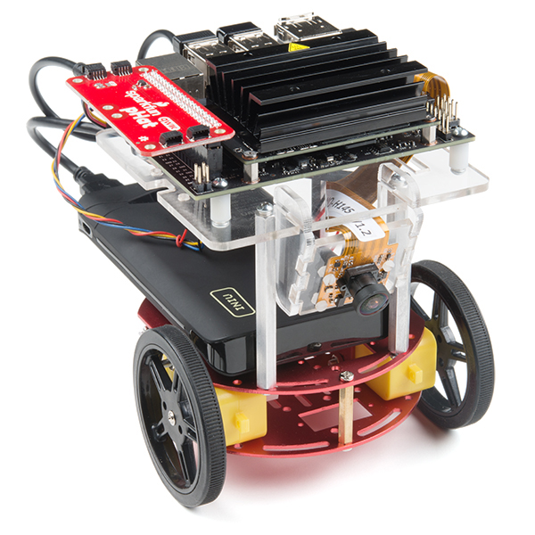
SparkFun’s version of the JetBot merges the industry leading machine learning capabilities of the NVIDIA Jetson Nano with the vast SparkFun ecosystem of sensors and accessories. Packaged as a ready to assemble robotics platform, the SparkFun JetBot Kit requires no additional components or 3D printing to get started – just assemble the robot, boot up the Jetson Nano, connect to WiFi and start using the JetBot immediately. This combination of advanced technologies in a ready-to-assemble package makes the SparkFun JetBot Kit a standout, delivering one of the strongest robotics platforms on the market. This guide serves as hardware assembly instructions for the two kits that SparkFun sells; Jetbot including Jetson Nano & the Jetbot add-on kit without the NVIDIA Jetson Nano. The SparkFun JetBot comes with a pre-flashed micro SD card image that includes the Nvidia JetBot base image with additional installations of the SparkFun Qwiic Python library, Edimax WiFi driver, Amazon Greengrass, and the JetBot ROS. Users only need to plug in the SD card and set up the WiFi connection to get started.
Note: We recommend that you read all of the directions first, before building your Jetbot. However, we empathize if you are just here for the pictures & a general feel for the SparkFun Jetbot. We are also those people who on occasion void warranties & recycle unopened instructions manuals. However, SparkFun can only provide support for the instructions laid out in the following pages.
Attention: The SD card in this kit comes pre-flashed to work with our hardware and has the all the modules installed (including the sample machine learning models needed for the collision avoidance and object following examples). The only software procedures needed to get your Jetbot running are steps 2-4 from the Nvidia instructions (i.e. setup the WiFi connection and then connect to the Jetbot using a browser). Please DO NOT format or flash a new image on the SD card; otherwise, you will need to flash our image back onto the card.
If you accidentally make this mistake, don’t worry. You can find instructions for re-flashing our image back onto the SD card in the software section of the guide
The Jetson Nano Developer Kit offers extensibility through an industry standard GPIO header and associated programming capabilities like the Jetson GPIO Python library. Building off this capability, the SparkFun kit includes the SparkFun Qwiic pHat for Raspberry Pi, enabling immediate access to the extensive SparkFun Qwiic ecosystem from within the Jetson Nano environment, which makes it easy to integrate more than 30 sensors (no soldering and daisy-chainable).
The SparkFun Qwiic Connect System is an ecosystem of I2C sensors, actuators, shields and cables that make prototyping faster and less prone to error. All Qwiic-enabled boards use a common 1mm pitch, 4-pin JST connector. This reduces the amount of required PCB space, and polarized connections mean you can’t hook it up wrong.
Materials
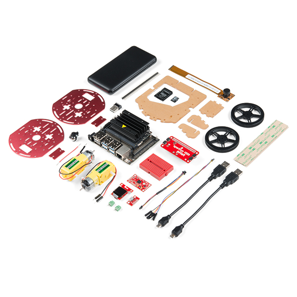
The SparkFun Jetbot Kit contains the following pieces; roughly top to bottom, left to right.
| Part | Qty |
|---|---|
| Circular Robotics Chassis Kit (Two-Layer) | 1 |
| Lithium Ion Battery Pack – 10Ah (3A/1A USB Ports) | 1 |
| Ball Caster Metal – 3/8″ | 1 |
| Edimax 2-in-1 WiFi and Bluetooth 4.0 Adapter | 1 |
| Header – male – PTH – 40 pin – straight | 1 |
| 2 in – 22 gauge solid core hookup wire (red) | 1 |
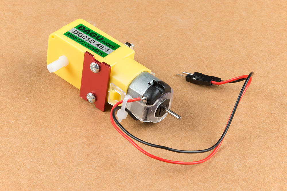
| Shadow Chassis Motor (pair) | 1 |
| Jetson Dev Kit (Optional) | 1 |
| SparkFun JetBot Acrylic Mounting Plate | 1 |
| SparkFun Jetbot image (Pre Flashed) | 1 |
| Leopard Imaging 145 FOV Camera | 1 |
| Screw Terminals 2.54mm Pitch (2-Pin) | 2 |
| SparkFun Micro OLED Breakout (Qwiic) | 1 |
| SparkFun microB USB Breakout | 1 |
| SparkFun Serial Controlled Motor Driver | 1 |
| Breadboard Mini Self-Adhesive Red | 1 |
| SparkFun Qwiic HAT for Raspberry Pi | 1 |
| SparkFun JetBot Acrylic sidewall for camera mount | 2 |
| SparkFun JetBot Acrylic Camera mount & 4x nylon mounting hardware | 1 |
| Qwiic Cable – 100mm | 1 |
| Qwiic Cable – Female Jumper (4-pin) | 1 |
| Wheels & Tires – included as part of circular robotics chassis | 2 |
| USB Micro-B Cable – 6″ | 2 |
| Dual Lock Velcro | 1 |
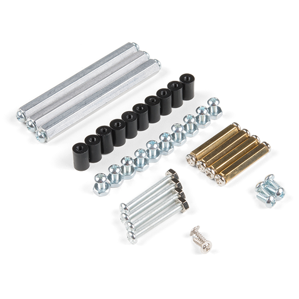
The SparkFun Jetbot Kit contains the following hardware; roughly top to bottom, left to right.
| Part | Qty |
|---|---|
| Hex Standoff #4-40 Alum 2-3/8″ | 3 |
| Standoff – Nylon (4-40; 3/8in.) | 10 |
| 1/4″ Phillips Screw with 4-40 Thread | 20 |
| Machine Screw Nut – 4-40 | 10 |
| Circular Robotics Chassis Kit (Two-Layer) Hardware | 1 |
Recommended Tools
We did not include any tools in this kit because if you are like us you are looking for an excuse to use the tools you have more than needing new tools to work on your projects. That said, the following tools will be required to assemble your SparkFun Jetbot.
- Small phillips & small flat head head screwdriver will be needed for chassis assembly & to tighten the screw terminal connections for each motor. We reccomend the Pocket Screwdriver Set; TOL-12268.
- Pair of scissors will be needed to cut the adhesive Dual Lock Velcro strap to desired size; recommended, but not essential..
- Soldering kit for assembly & configuration of the SparkFun Serial Controlled Motor Driver – example TOL-14681
- Optional– adjustable wrench or pliers to hold small components (nuts & standoffs) in place while tightening screws; your finger grip is usually enough to hold these in place while tightening screws & helps to ensure nothing is over tightened.A Note About Directions
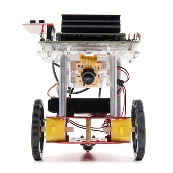
When we talk about the ”front,” or ”forward” of the JetBot, we are referring to direction the camera is pointed when the Jetbot is fully assembled. ”Left” and ”Right” will be from the perspective of the SparkFun Jetbot.
1. Circular Robotics Chassis Kit (Two-Layer) Assembly
If you prefer to follow along with a video, check out this feature from the chassis product page. You do not need to use the included ball caster as a larger option has been provided for smoother operation.
Start by attaching the chassis motor mount tabs to each of the ”Shadow Chassis Motors (pair)” using the long threaded machine screws & nuts included with the Circular Robotics Chassis Kit.
Fit the rubber wheels onto the hubs, install the wheel onto each motor, & fix them into position using the self tapping screws included with the Circular Robotics Chassis Kit.

Install the brass colored standoffs included with the Circular Robotics Chassis Kit; two in the rear and one in the front. The rear of the SparkFun Jetbot will be on the side of the plate with the two ”+” sign cut outs. The rear of the motor will be opposite the wheel where the spindle extends. This orientation ensures the widest base & most stable set up for your Jetbot.

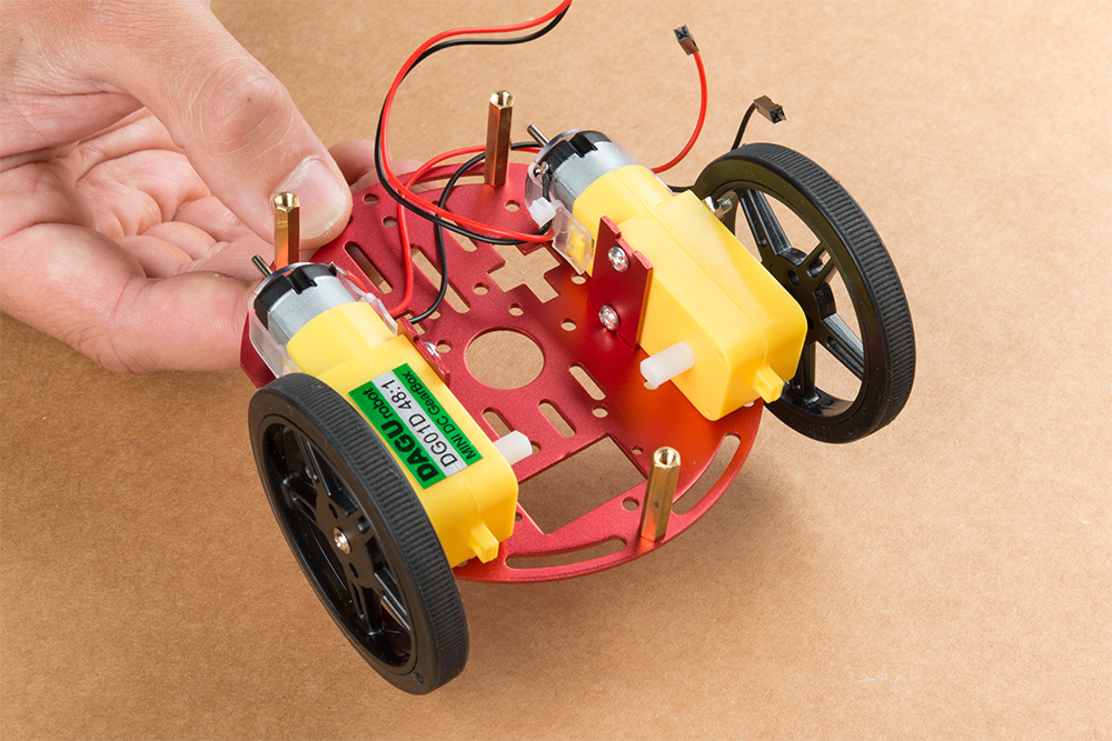
The motor mounts fit into two mirrored inlets in each base plate as shown. Install the motors opposite of one another.
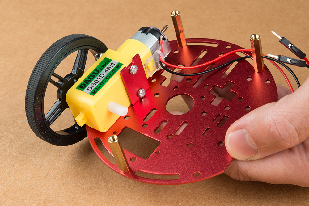
Depending on how you install the motor mounts to each motor will dictate how the motor can be installed on the base plate. Note: Do not worry about the motor orientation as you will determine proper motor operation in how you connect the motor leads to the SparkFun Serial Controlled Motor Driver. Notice how in the picture below one motor has the label facing up, while the other has the label facing down.
Place the other circular robot chassis plate on top of and align the two ”+” and the motor mount tab recesses. Hold the sandwiched chassis together with one hand and install the remaining Phillips head screws included with the Circular Robotics Chassis Kit through the top plate & into the threaded standoffs.
Your main chassis is now assembled! The Circular Robotics Chassis Kit also contains a very small caster wheel assembly, but we have included a larger metal caster ball to increase the stability of the SparkFun Jetbot. We will cover the installation of this caster ball later in the tutorial.

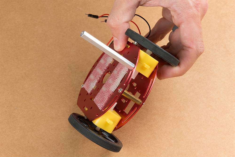
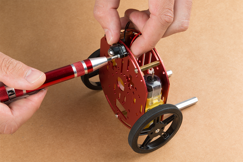
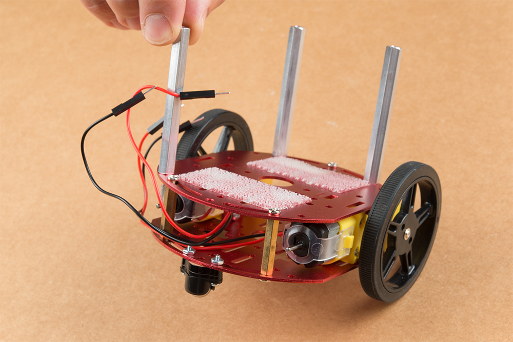
Utilize three of the included 1/4 in 4-40 Phillips Screws through the top chassis plate with threads facing up & install the 2-3/8 in #4-40 Aluminum Hex Standoff until they are finger tight.
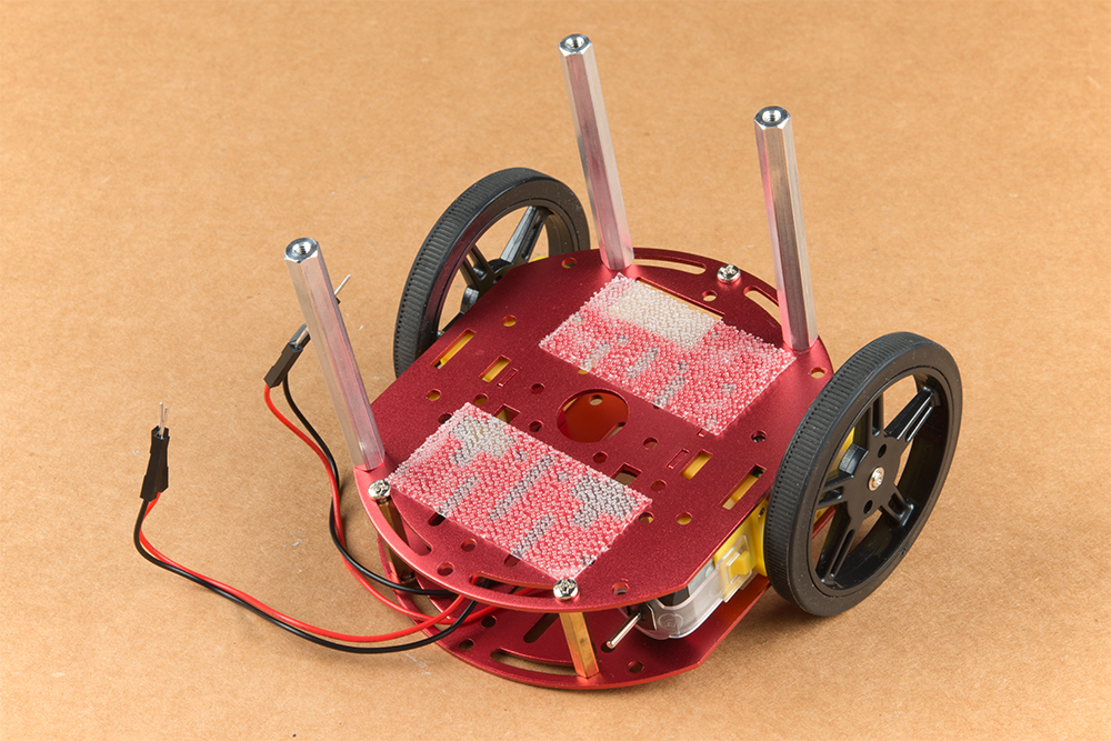
The aluminum stand offs should be pointing up as shown below.
The SparkFun JetBot acrylic mounting plate is designed to have two of these aluminum standoffs in the front & one in the rear. We recommend the rear standoff on the left side of the chassis (as shown) so the 6 in microB usb cables that will be installed later can more easily span the gap needed to power the JetBot.
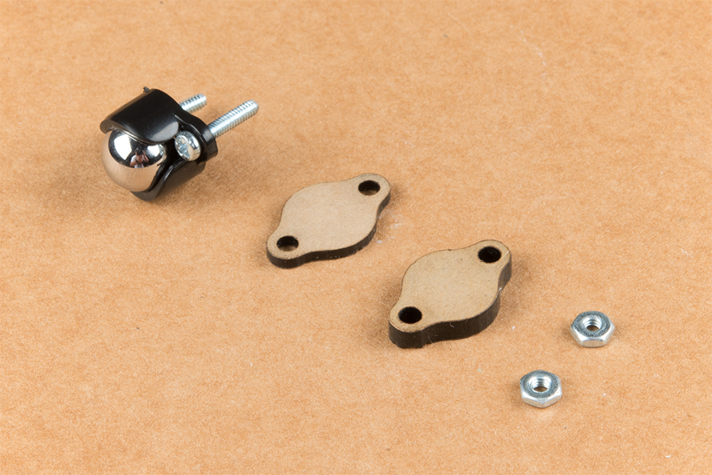
Un-package the 3/8 in Metal Caster Ball and thread the mounting screws through all pieces as shown. Note the full stack height will help balance the Jetbot in a stable position.
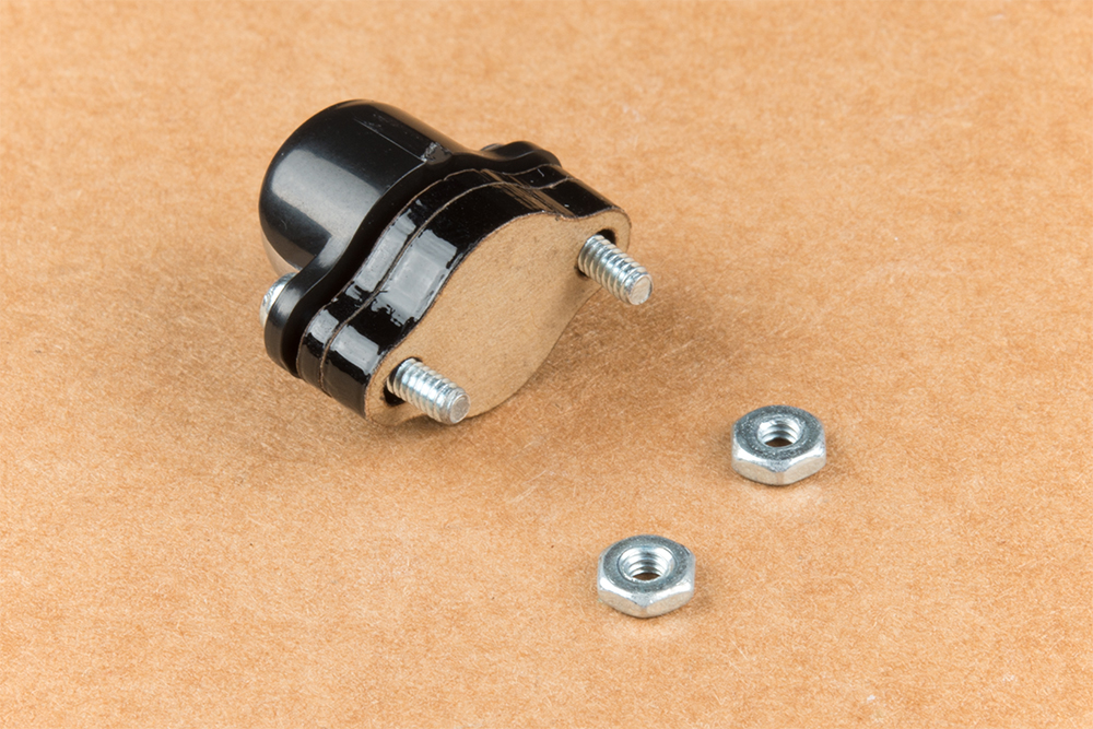
Install the caster wheel using the Phillips head screws and nuts included with the 3/8 in caster ball assembly. The holes on the caster assembly are spaced to fit snug on the innermost segment of the angular slots near the rear of the lower plate on the JetBot chassis. Again, hand tight is just fine. Note: if you over tighten these screws it will prevent the ball from easily rotating in the plastic assembly. However, too loose and it may un-thread; go for what feels right
After you have installed the caster & aluminum standoffs, thread the motor wires through the back of the chassis standoffs for use later.
2. Camera Assembly & Installation
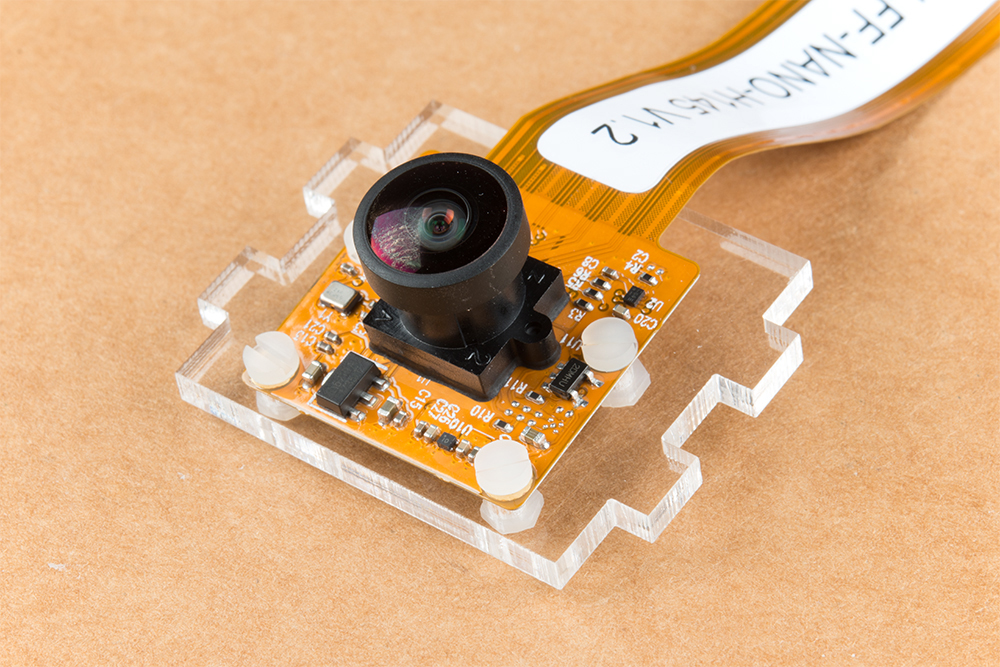
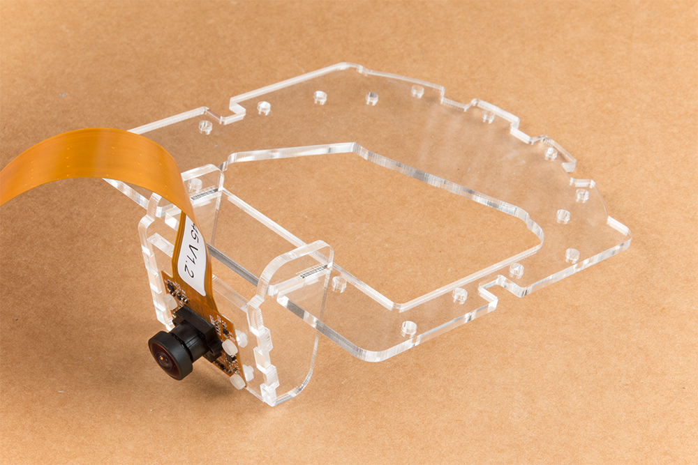
Unpackage the Leopard Imaging camera & align the four holes in the acrylic mounting plate with those on the camera.
Note: ensure that the ribbon cable is extending over the acrylic plate on the edge that does not have mounting holes near the edge; as shown below.
Place all four nylon flathead screws through the camera & acrylic mounting plate prior to fully tightening the nylon nuts. This will ensure equal alignment across all four screws. Tighten the screws while holding the nuts with finger pressure in a rotating criss cross pattern; similar to how you tighten lug nuts on a car rim.
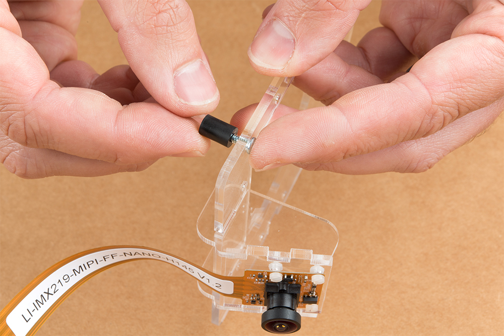
Align one acrylic sidewall with the camera mounting plate as shown below ensuring that the widest section of the sidewall is oriented to the top of the camera mount where the ribbon cable extends.
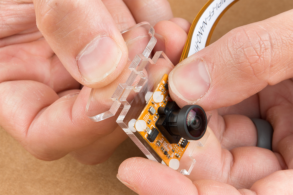
Apply even pressure on each piece until they fit together. Note: these pieces are designed to have an interference fit and will have a nice, satisfying ”click” when they fit together.

Repeat this process on the other side to fully assemble the camera mount.

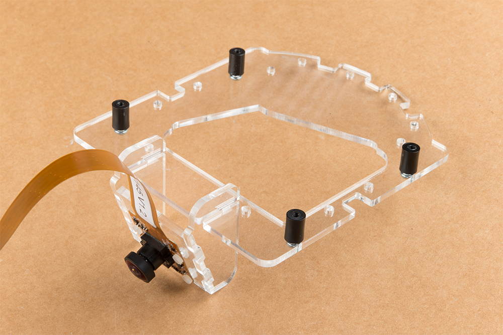
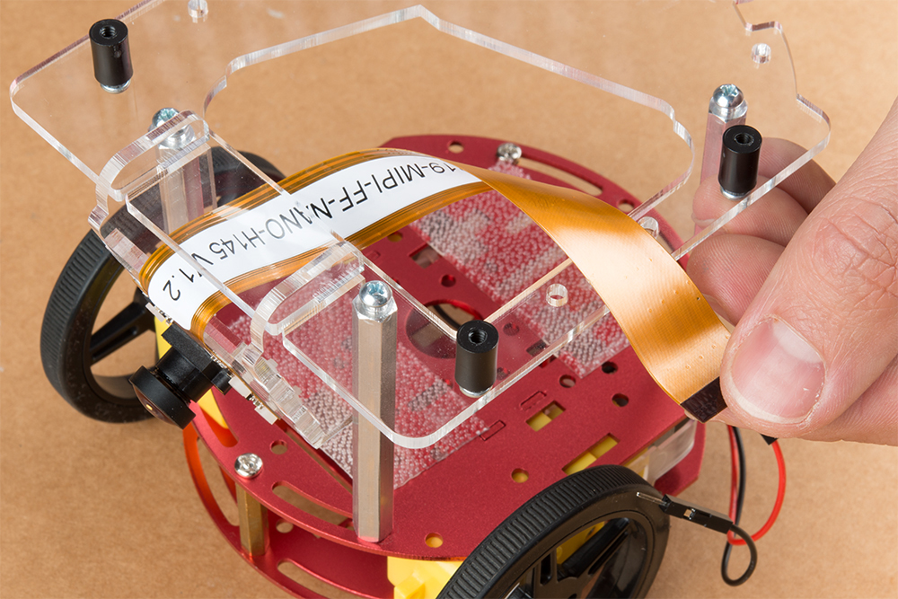
The camera mount should now be installed to the SparkFun Jetbot acrylic mounting plate using the overlapping groove joints. Ensure that the cut out on the acrylic mounting plate is facing towards the front/right of the Jetbot as shown. This will ensure that there is plenty of room for the camera ribbon cable to pass around the assembly and up to the Jetson nano camera connector.
Install four of the nylon standoffs to the top of the SparkFun Jetbot acrylic mounting plate using four of the included 1/4 in 4-40 Phillips head screws as shown below.
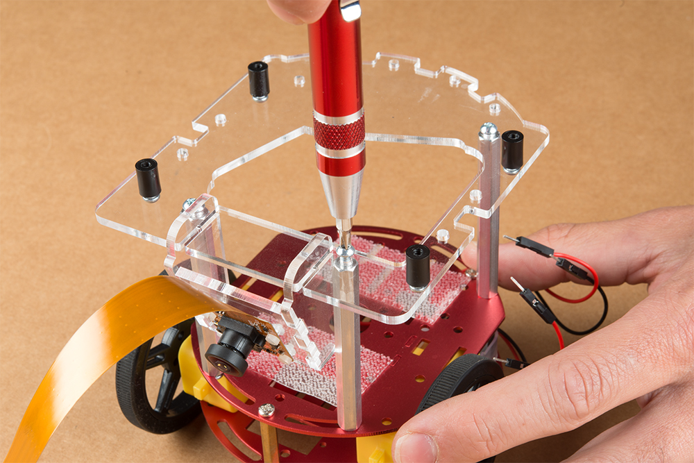
Utilize three more of the 1/4 in 4-40 Phillips head screws to install the SparkFun Jetbot acrylic mounting plate to the aluminum standoffs extending from the Two-layer circular robotics chassis as shown below.
3. Motor Driver Assembly & Configuration
To get started, make sure that you are familiar with the SparkFun Serial Controlled Motor Driver Hookup Guide.
We also recommend a detailed review of the Hardware Overview of the SparkFun Serial Controlled Motor Driver Here.

You will need to solder both triple jumpers labeled below as ”I2C pull-up enable jumpers” as the SparkFun pHat utilizes the I2C protocol. The default I2C address that is used by the pre-flashed SparkFun Jetbot image is 0x5D which is equavalent to soldering pad #3 noted as ”configuration bits” on the back of the SparkFun serial controlled motor driver; see below. You will need to create a solder jumper on pad #3 only for the SparkFun Jetbot Image to work properly.
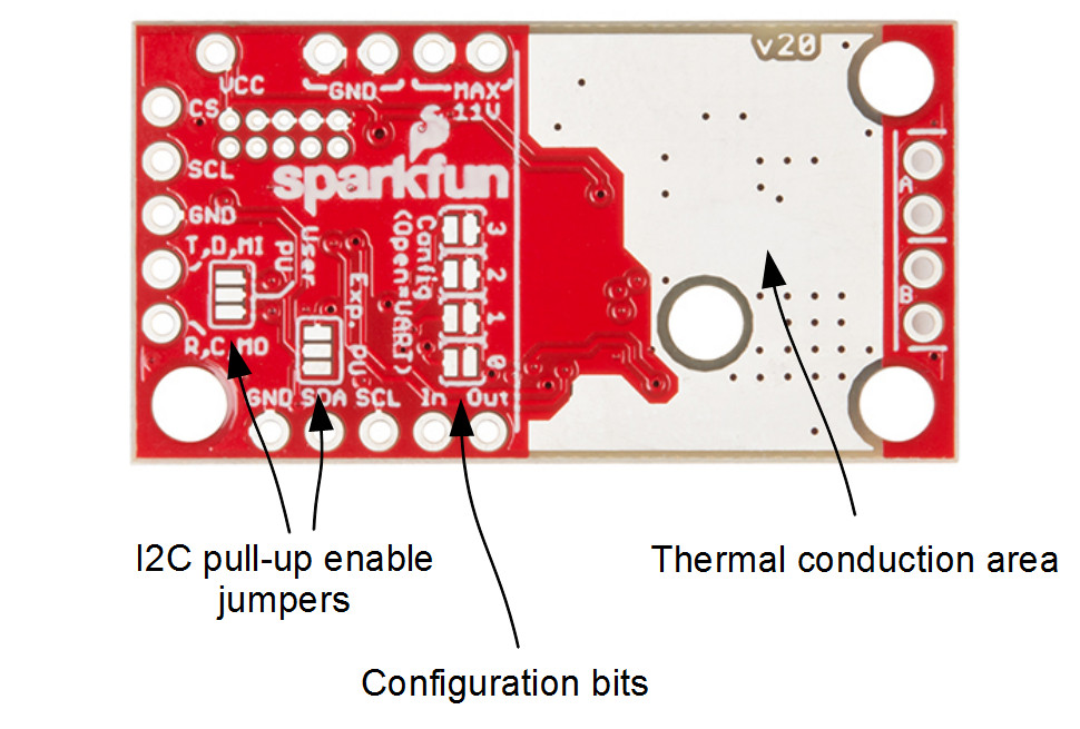
Layout of jumpers on the Serial Controlled Motor Driver.
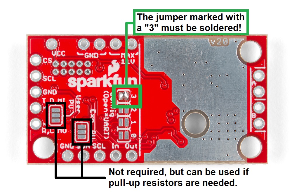
Jumper 3 of theConfiguration Bitsproperly soldered.
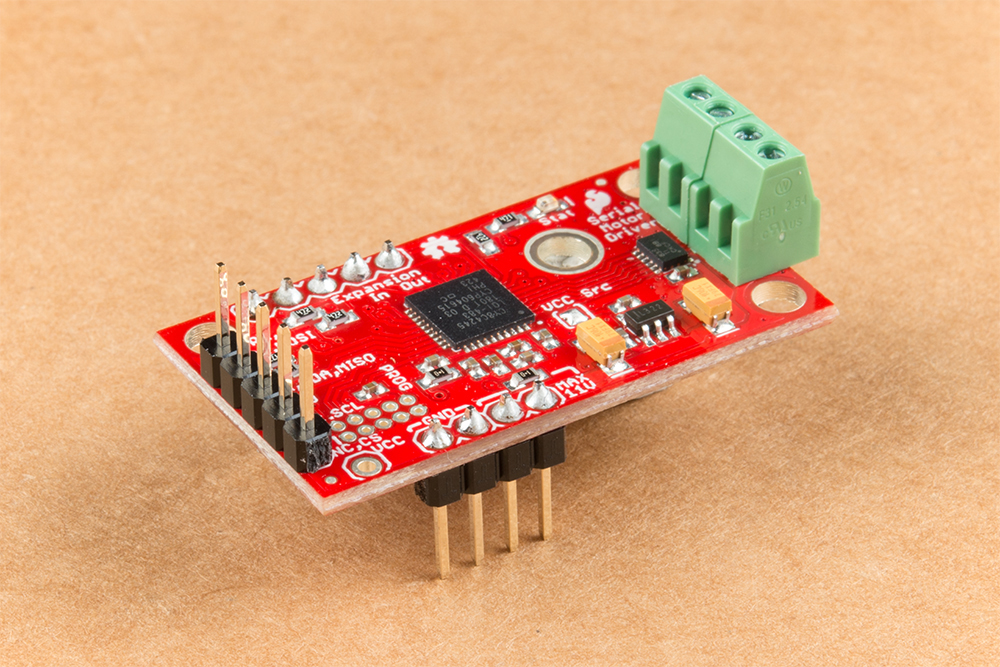
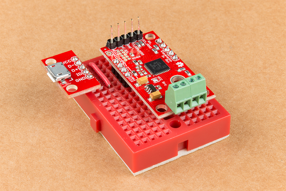
Your completed Serial Controlled motor drive should look somewhat similar to the board shown below.
- The 2-pin screw terminals are soldered to the ”Motor Connections.”
- Break off 4 Male PTH straight headers and solder into the ”Power (VIN) connection” points.
- Break off 5 Male PTH straight headers and solder into the ”Expansion port” points. These will not be used, but will provide additional board stability when installed into the mini breadboard.
- Break off 5 Male PTH straight headers and solder into the ”User port” points for connection into the included Female Jumper Qwiic cables.

Break off 5 Male PTH straight headers and solder into the breakout points on the SparkFun microB USB Breakout.
Install both the SparkFun Serial Controlled Motor Driver & the SparkFun microB Breakout board on the included mini breadboard so the ”GRD” terminals for each unit share a bridge on one side of the breadboard.
Utilize the included 2 in – 22 gauge solid core hookup wire (red) to bridge the ”VCC” pin for the SparkFun microB Breakout to either (VIN) connection point on the SparkFun Serial Controlled Motor Driver as shown below.
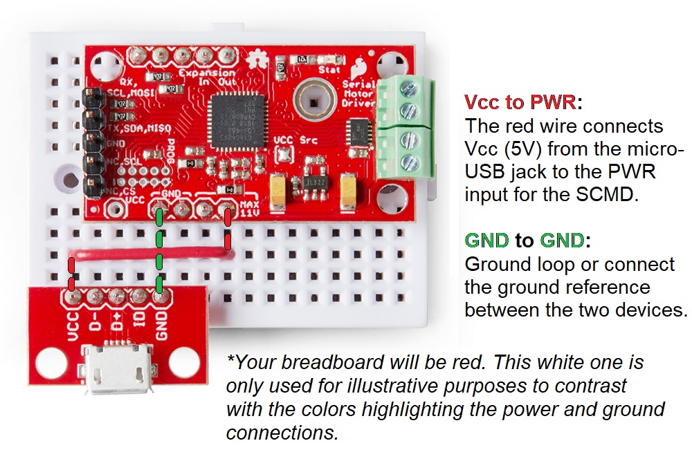
Required power connections between the micro-USB breakout and the Serial Controlled Motor Driver.
Competed assembly of the micro-USB breakout and Serial Controlled Motor Driver on the breadboard.
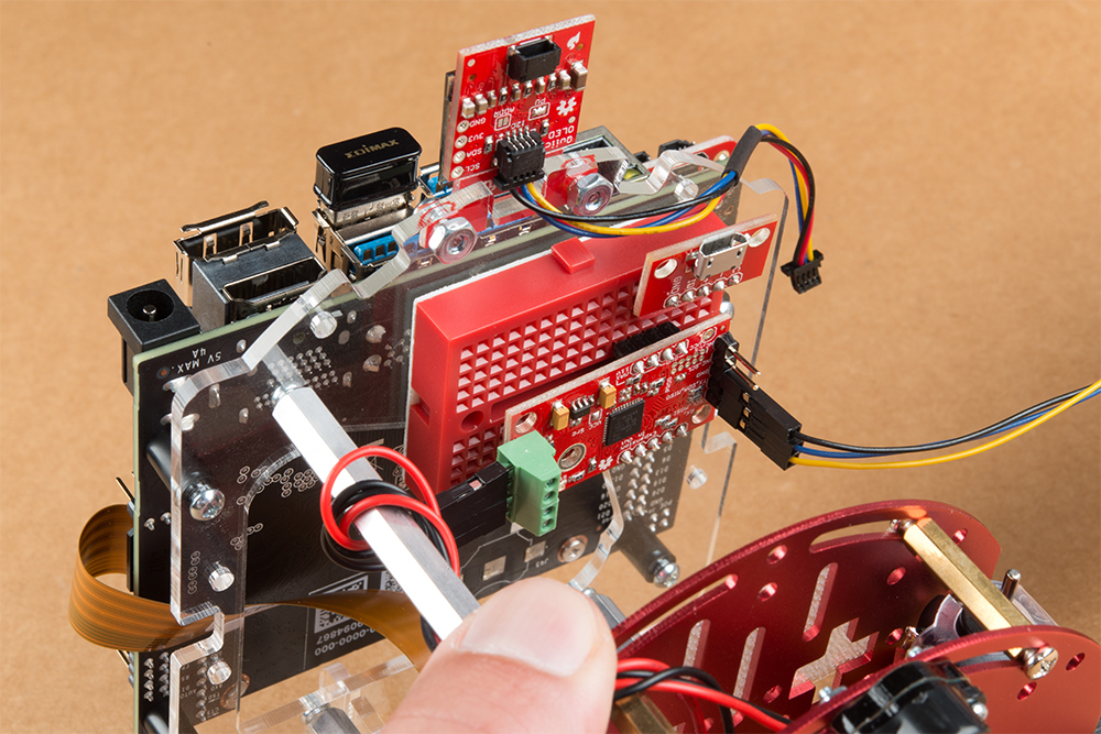
Utilize a small flat head screwdriver to loosen the four connection points on the screw terminals. When inserting the motor connection wires, note the desired output given the caution noted in section #1 of this assembly guide.
Note from section #1: Do not worry about the motor orientation as you will determine proper motor operation in how you connect the motor leads to the SparkFun Serial Controlled Motor Driver.
These connection points can be corrected when testing the robot functionality. If your Jetbot goes straight when you expect Jetbot to turn or vice versa, your leads need to be corrected.
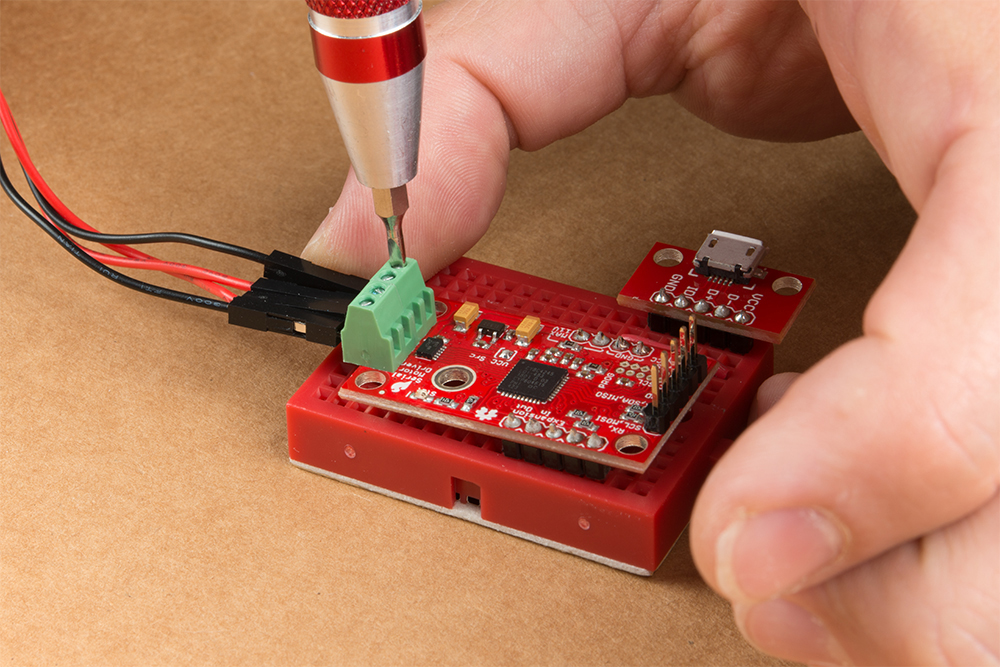
Set this assembly aside for full installation later.
4. Accessory Installation to Main Chassis
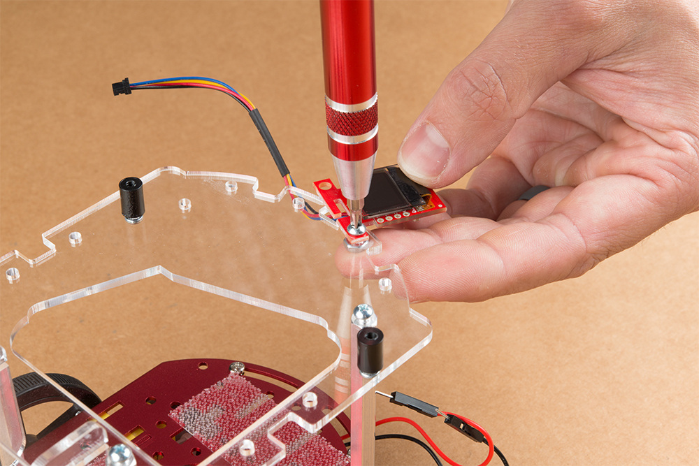
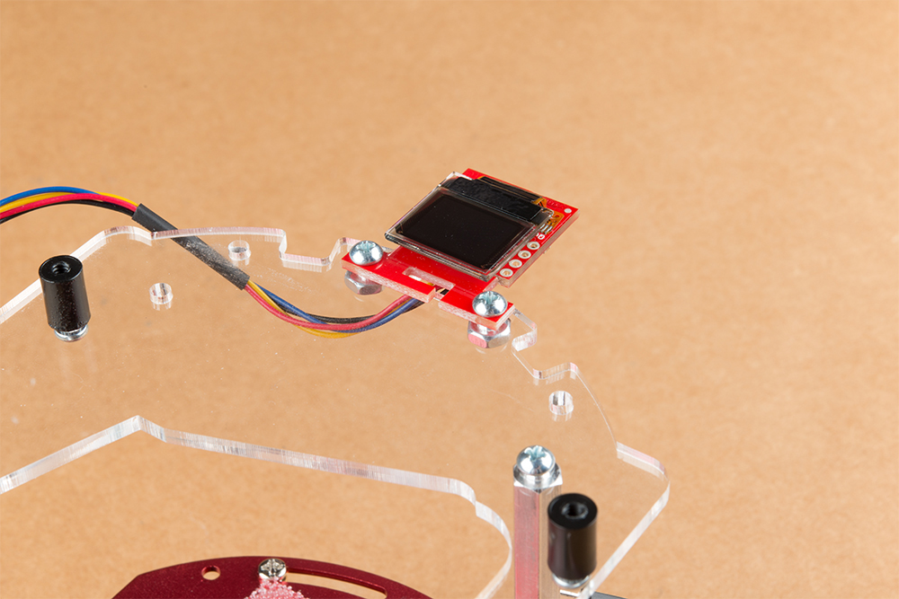
Align the mounting holes on the SparkFun Micro OLED (Qwiic) with those on the back of the SparkFun Jetbot acrylic mounting plate. Install the Micro OLED using two 1/4 in 4-40 Phillips head screws and two 4-40 machine screw nuts.
Thread the ribbon cable of the Leopard imaging camera back through the acrylic mounting plate and half-helix towards the left side of the Jetbot.
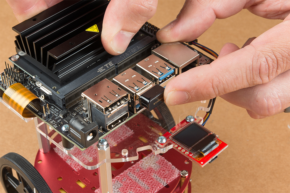
Install the Jetson Nano Dev kit to the nylon standoffs using four 1/4 in 4-40 Phillips head screws. Tighten each screw slightly in a criss-cross pattern to ensure the through holes do not bind during install until finger tight. Make sure you can still access the camera ribbon cable.

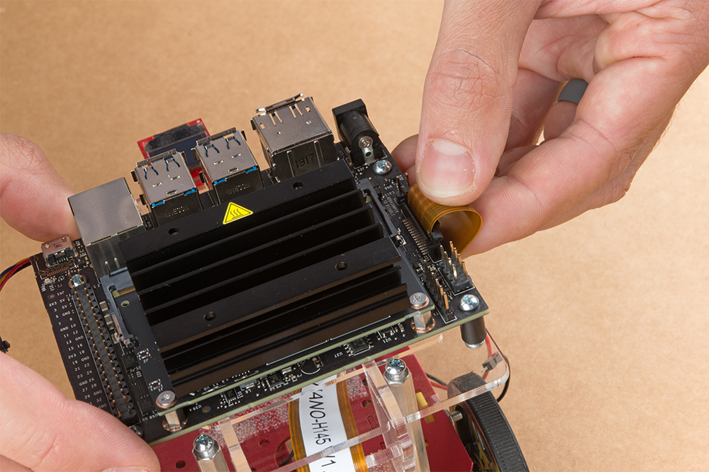
Note: the camera connector is made from small plastic components & can break easier than you think. Please be careful with this next step.
Loosen the camera connector with a fingernail or small flathead screwdriver. Fit the ribbon cable into this connector and depress the plastic press fit piece of the connector to hold the ribbon cable in place.
Unpackage & install the USB Wifi adaptor into one of the USB ports on the Jetson nano Dev Kit. The drivers for this Wifi adaptor are pre-installed on the SparkFun Jetbot image. If you are making your own image, you will need to ensure you get these from Edimax.
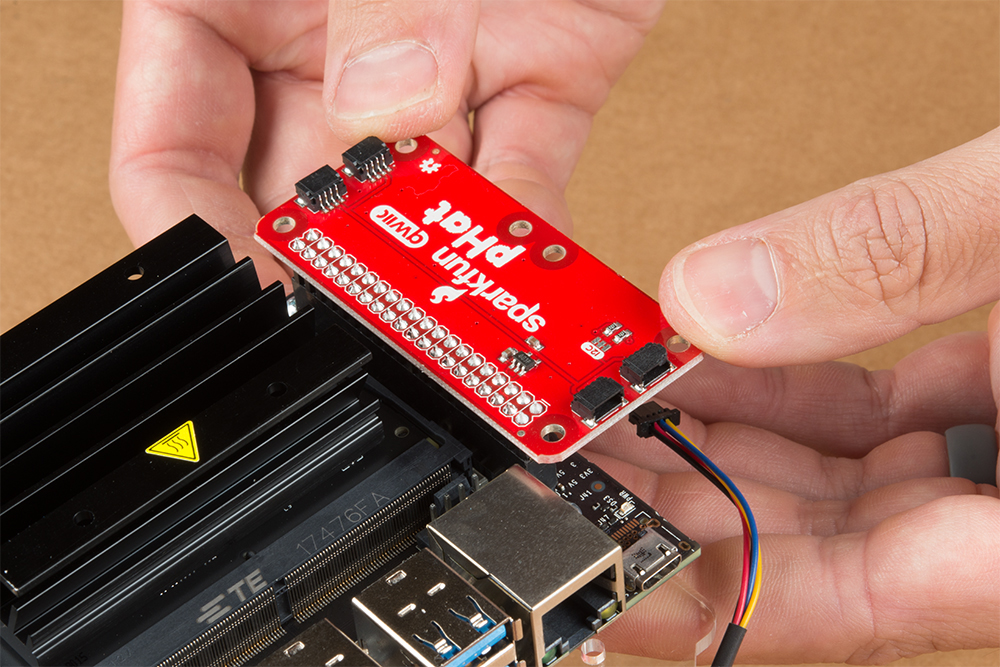
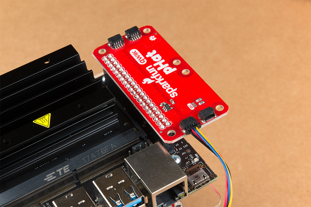
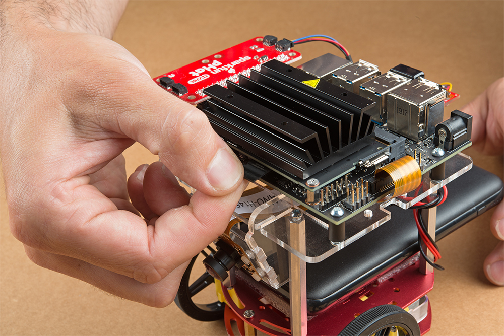
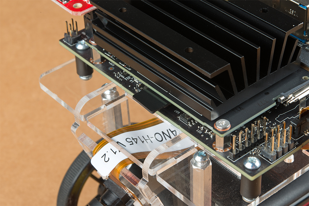
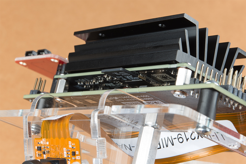
Align the SparkFun pHat with the GPIO headers on the Jetson Nano Dev Kit so that the pHat overhangs the right hand side of the Jetbot. For additional information on hardware assembly of the SparkFun pHat, please reference the hookup guide here.
Note: The heatsink on the Jetson Nano Dev Kit will only allow for one orientation of the SparkFun pHat.
Wrap the motor wires around the rear/left standoff to take up some of the slack; one or two passes should do. Peel the cover off the self adhesive backing on the mini breadboard you set aside at the end of section #3.
Place the breadboard near the back of the Jetbot Acrylic mounting plate where there is good adhesion & access to all the components. Attach the (4-pin) Female Jumper Qwiic cable to the SparkFun Serial Controlled Motor Driver pins as shown. Yellow to ”SCL,” Blue to ”SDA,” Black to ”GND.”
Daisy chain the polarized Qwiic connector on the other end of the (4-pin) Female Jumper Qwiic cable into the back of the SparkFun Micro OLED (Qwiic).
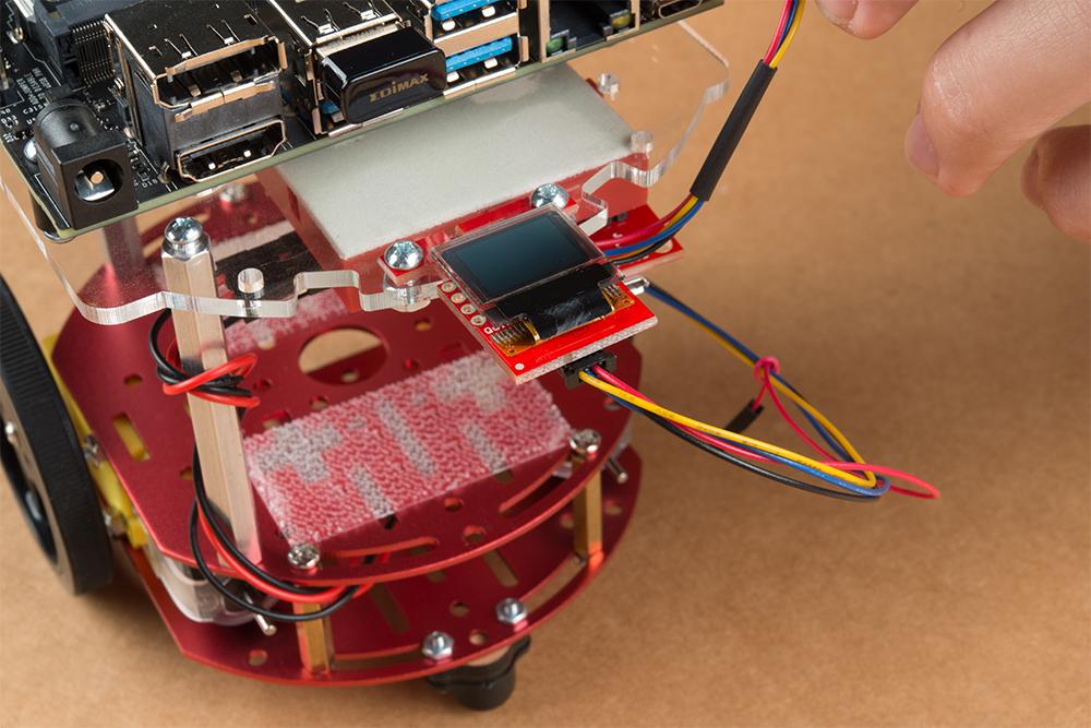
Using the 100mm Qwiic Cable attach the SparkFun Micro OLED front Qwiic connector to the SparkFun pHat as shown.
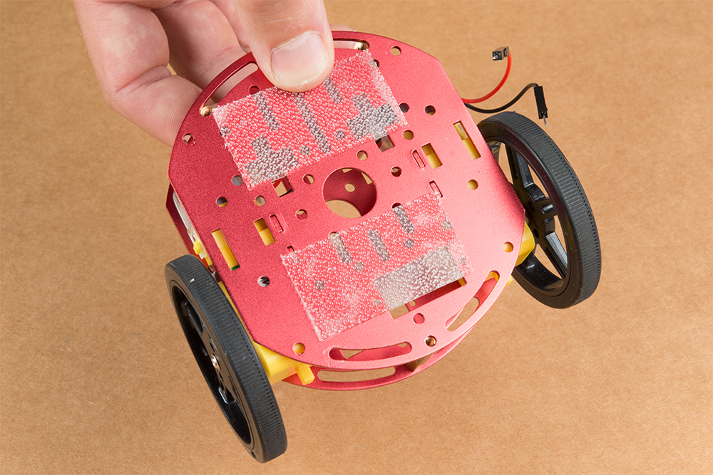
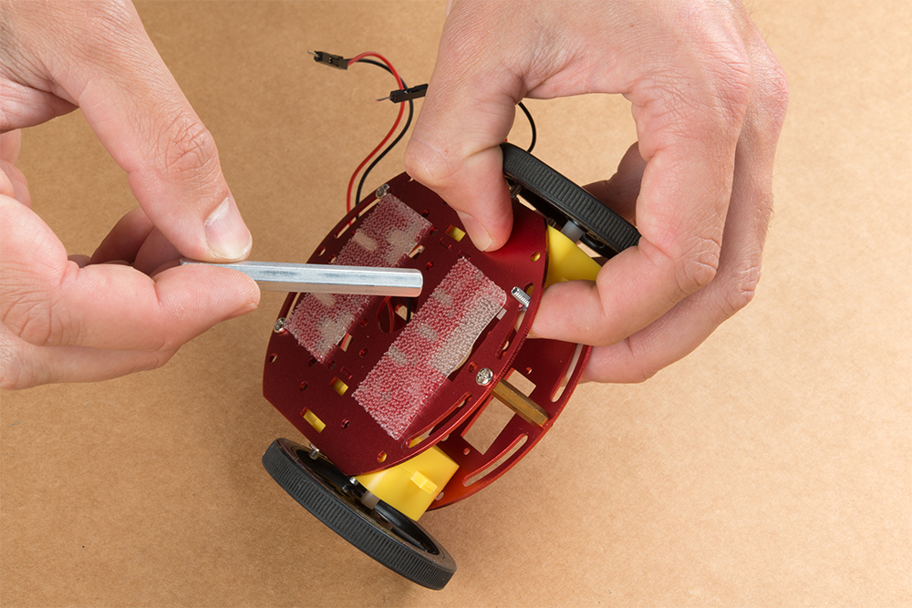
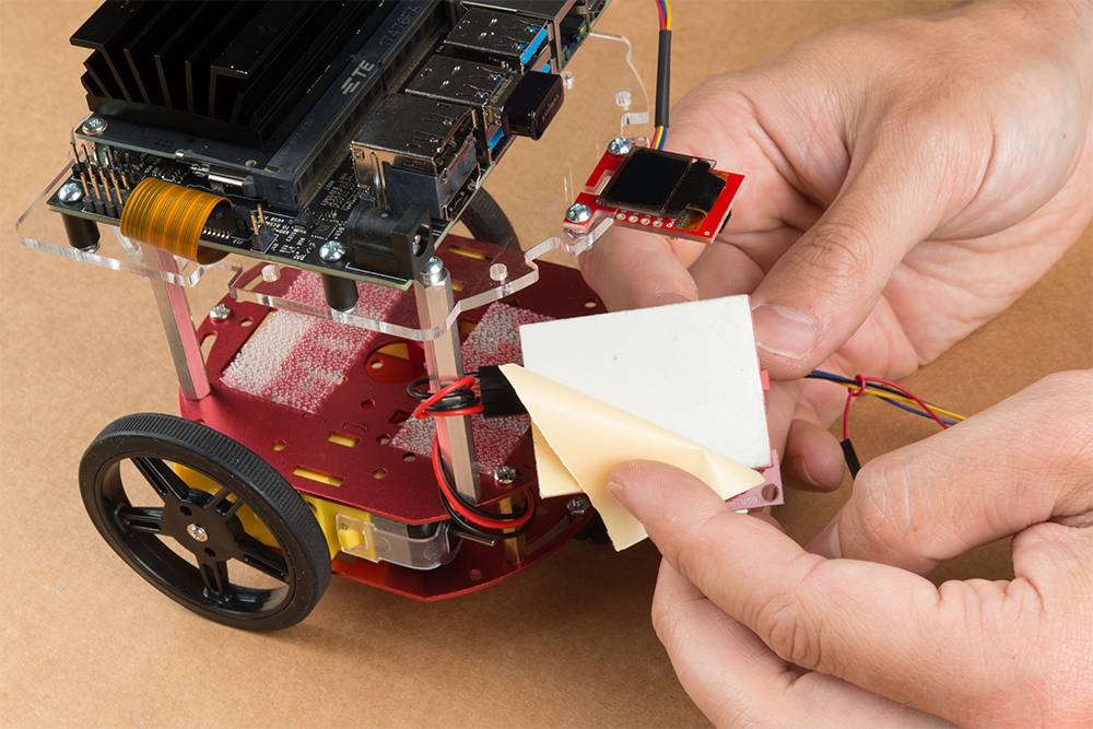
Cut the Dual Lock Velcro into two pieces and align them on the 10Ah battery & top plate of the Two-Layer Circular Robotics Chassis as shown below. Ensure that the USB ports on the battery pack are pointing out the back of the Jetbot. Additionally, the orange port (3A) will need to power the Jetson Nano Dev Kit & therefore will need to be on the right side of the Jetbot.

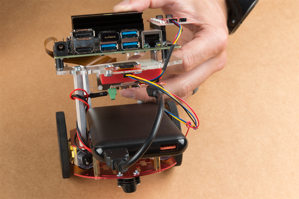
Apply firm pressure to the battery pack to attach to the Jetbot chassis via the Dual Lock Velcro.
Remove the micro SD card from the SD card adapter.
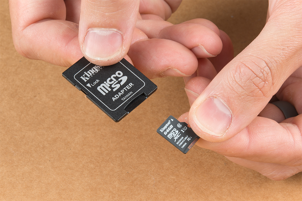
Insert the micro SD card facing down into the micro SD card slot on the front of the Jetson Nano Dev Kit. Please see the next three pictures for additional details.
The USB ports on the back of the 10Ah battery pack has two differently colored ports. The black port (1A) is used to power the motor driver via the SparkFun microB breakout. Utilize one of the 6 in micro-B USB cables to supply power to the microB breakout.

Note: Once you plug the Jetson Nano Dev Kit into the 3A power port, this will ”Boot Jetson Nano” which is not covered in detail until the links in section #5 of this assembly guide. Do not proceed unless you are ready to move forward with the software setup & examples provided by NVIDIA.
The orange port (3A) is used to power the Jetson Nano Dev Kit. Utilize the remaining 6 in micro-B USB cable to supply power to the Jetson Nano Dev Kit.

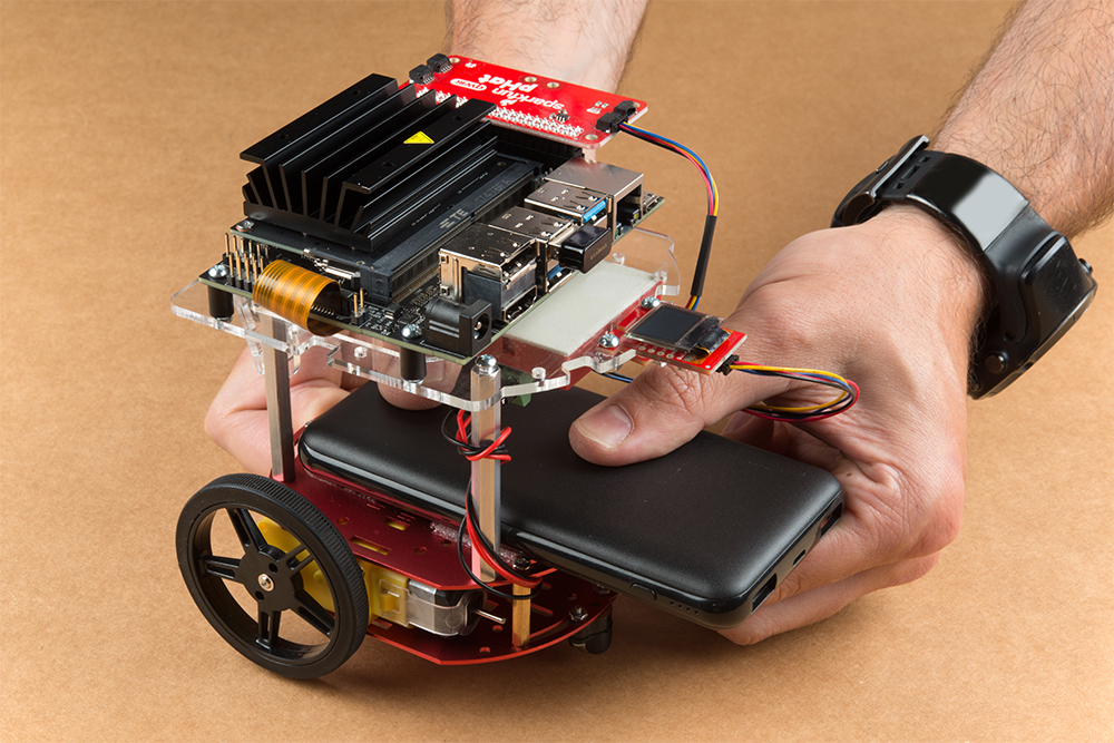
Congratulations! You have fully assembled your SparkFun JetBot AI Kit!
5. Software Setup Guide from NVIDIA
Attention: The SD card in this kit comes pre-flashed to work with our hardware and has the all the modules installed (including the sample machine learning models needed for the collision avoidance and object following examples). The only software procedures needed to get your Jetbot running are steps 2-4 from the Nvidia instructions (i.e. setup the WiFi connection and then connect to the Jetbot using a browser). Please DO NOT format or flash a new image on the SD card; otherwise, you will need to flash our image back onto the card (instructions below).
Your SparkFun Jetbot comes with a Pre-Flashed micro SD card. Users only need to plug in the SD card and set up the WiFi connection to get started.
- The default password on everything (i.e. login/user, jupyter notebook, and superuser) is ”jetbot”.
- We recommend that users change their passwords after initial setup. These are typically covered on the first boot of your Jetson Nano as detailed in the NVIDIA Getting Started with Jetson Nano walkthrough
Software Setup
The only steps needed to get your Jetbot kit up and running is to log into the Jetbot and setup your WiFi connection. Once that is done, you are now ready to connect to the Jetbot wirelessly. If you need instructions for doing so, you can use the link below.However, please take note of our instructions below. You will want to skip steps 1 and 5 to avoid erasing the image on the card or undoing the hardware configuration.NVIDIA JETBOT WIKI SOFTWARE SETUP
Instructions
- Skip step 1 of Nvidia’s instructions: It references how to flash your SD card, so feel free to skip to Step 2 – Boot Jetson Nano.
Note: Following Step 1 will erase the pre-flashed image and make a lot of extra work for yourself.
- Skip step 5 of Nvidia’s instructions: This step should already be setup on the pre-flashed SD card.
- If in the future, you need to update your notebooks, make sure that if you are following Step 5 – Install latest software (optional), skip the last command line instruction of the forth step.
Get and install the latest JetBot repository from GitHub by entering the following commands
COPY CODEgit clone https://github.com/NVIDIA-AI-IOT/jetbot
cd jetbot
sudo python3 setup.py install
Note:Running sudo python3 setup.py install in the command line will overwrite the software modifications for SparkFun’s hardware in the kit.
Troubleshooting
In the event that you accidentally missed the instructions above, here are instructions to get back on track.
Re-Flashing the SD card
If you need to re-flash your SD card, follow the instructions from Step 1 Nvidia’s guide. However, download and use our image instead (click link below).DOWNLOAD SPARKFUN’S JETBOT IMAGENote: Don’t forget to uncompress (i.e. unzip, extract, or expand) the file from the .zip file/folder first. You should be pointing the ”flashing” software to an ~62GB .img file to flash the image (sparkfun_jetbot_v01-00.img) onto the SD card.
Alternatively, there are other options for flashing images onto an SD card. If you have a preferred method, feel free to use the option you are most comfortable with.
Re-Applying the Software Modifications
If you have accidentally, overwritten the software modifications for the hardware included in your kit, you will need to repeat Step 5 from Nvidia’s guide from the desktop interface (if you are comfortable performing the following steps from the command line, feel free to do so).
Skip steps 1 and 2: Plug in a keyboard, mouse, and monitor. Then log in to the desktop interface (if you haven’t changed your password, the default password is: jetbot).
Follow step 3: Launch the terminal. There is an icon on sidebar on the left hand side. Otherwise, you can use the keyboard short cut (Ctrl + Alt + T).
Follow step 4: However, before you execute sudo python3 setup.py install you will want to copy in our file modifications to the jetbot directory you are in.
- Begin by downloading our files (click link below).
- Next, extract the file.
- Next, replace the files in the
jetbotfolder. The file paths must be the same, so make sure to overwrite files exactly.
Click on the icon that looks like a filing cabinet on the left hand side of the GUI. This is your Home directory. From here, you will need to proceed into the jetbot folder. There you will find a jetbot folder with similar files to the ones you just extracted. Delete the folder and copy in our files (you can also just overwrite the files as well).
- Now, you can execute
sudo python3 setup.py installin the terminal.
Follow step 5: Finish up by following step 5. Now you are back on track to getting your Jetbot running again!
6. Examples
The ”object following” jupyter notebook example won’t work due to the required dependencies that had not been released by NVIDIA prior to the creation of the SparkFun JetBot image. These updates can be manually installed on your Jetson Nano with the JetPack 4.2.1 release.
Update: The engine generated for the example utilized a previous version of TensorRT and is therefore, not compatible with the latest release. For more details on this issue, check out the following GitHub issue.NVIDIA JETBOT WIKI EXAMPLES
Resources and Going Further
Now that you’ve successfully got your JetBot AI up and running, it’s time to incorporate it into your own project!
For more information, check out the resources below:
- Getting Started With Jetson Nano Developer Kit
- Assembly Guide for SparkFun JetBot AI Kit
- SparkFun Hookup Guide for Serial Controlled Motor Driver
- SparkFun Hookup Guide for Micro OLED (Qwiic)
- SparkFun Hookup Guide for Qwiic pHAT
- Jetbot ROS GitHub Repository
- Getting Started with AWS IoT Greengrass
- NVIDIA Jetson Forums
- NVIDIA JetBot GitHub Issues
- NVIDIA JetBot GitHub
- NVIDIA JetBot GitHub Wiki
- NVIDIA JetBot software setup
Need some inspiration for your next project? Check out some of these related tutorials:
Easy Driver Hook-up Guide
Get started using the SparkFun Easy Driver for those project that need a little motion.
Servo Trigger Hookup Guide
How to use the SparkFun Servo Trigger to control a vast array of Servo Motors, without any programming!
SparkFun 5V/1A LiPo Charger/Booster Hookup Guide
This tutorial shows you how to hook up and use the SparkFun 5V/1A LiPo Charger/Booster circuit.
Wireless Remote Control with micro:bit
In this tutorial, we will utilize the MakeCode radio blocks to have the one micro:bit transmit a signal to a receiving micro:bit on the same channel. Eventually, we will control a micro:bot wirelessly using parts from the arcade:kit!