Det händer mycket i Oceanhamnen i Helsingborg nu.
Oceanhamnen är första etappen av stadsutvecklings-projektet H+ i Helsingborg som fram till år 2035 ska omvandla en miljon kvadratmeter gammalt hamn- och industriområde till de fyra stadsdelarna Oceanhamnen, Universitetsområdet, Husarområdet och Gåsebäck och ge plats för 10 000 nya invånare. Syftet är att skapa framtidens smarta hållbara stad och då behöver vi självklart involvera eleverna på Innovationsgymnasiet i Helsingborg!
Alla viktiga projekt behöver en flygande start!
Först ut på bollen är teknikeleverna i årskurs 2 (TE18DP) som läser Design, Konstruktion, CAD och produktutveckling som, förutom att skapa 3D-ritningar med inredningsförslag till blivande bostadsrätter, kontor och hotell, även kommer bygga fysiska 3D-modeller av de nya bostäderna. Teknikeleverna i årskurs 1 (TE19) är också med i projektet och kommer jobba med fasadritningar och bygga skalenliga modeller av fastigheternas fasader inom kursen Teknik 1.
TE18DP ska även designa och konstruera förslag på smarta, kompakta och mobila modulära studentbostäder av återbruksmaterial.
Som en naturlig del i projektet väver vi in innovativa tekniska lösningar för smarta hem, intelligenta byggnader med lokal energiåtervinning och system för användarcentrerad feedback i syfte att minska varje individs energi- och vattenförbrukning och avfallsmängd. För de projekt och produktidéer som rör IoT (Internet Of Things) och digitala lösningar kommer våra elever (TE18IM) som läser Dator- och Nätverksteknik, Programmering, Webbutveckling och certifieringskursen Cisco IoT Fundamentals Connecting Things involveras.
Genomgående för uppdragen är tillämpning av principer för hållbar design och användandet av moderna professionella digitala design- och konstruktionsverktyg som Blender, Sketchup, Fusion 360, Meshroom, Autodesk Revit, Unity, Unity Reflect samt 3D-skrivare och återbruksmaterial för att skapa skalenliga fysiska modeller.
Under våren kommer natureleverna (NA19), som en del av projektet ”TIS-Tema Vatten”, titta närmare på den nya innovativa vattenreningsanläggningen Reco Lab (se mer info nedan) som är en modell för framtidens avloppssystem som håller på att byggas i Oceanhamnen.
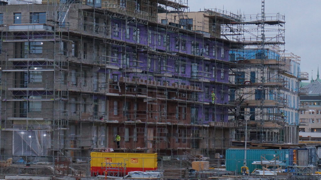
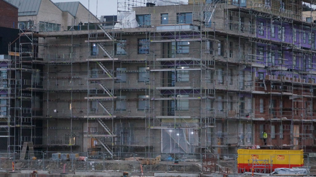
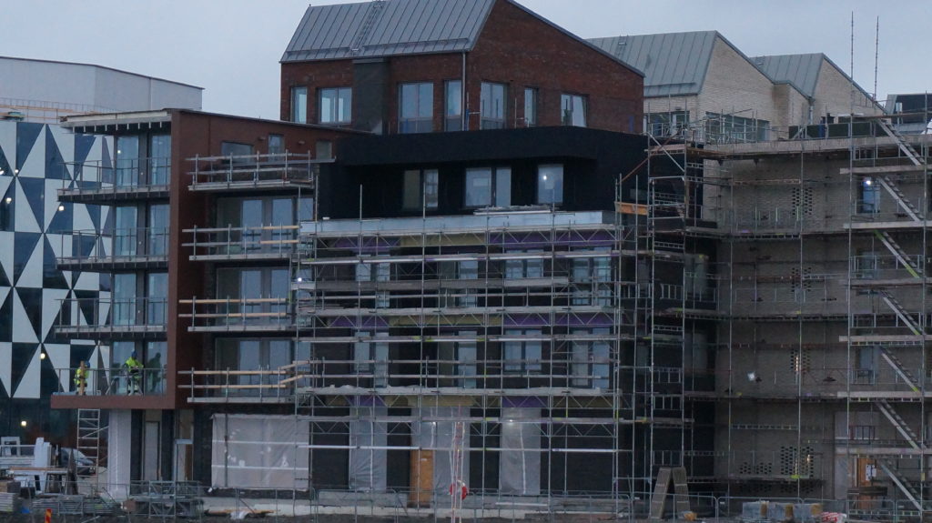
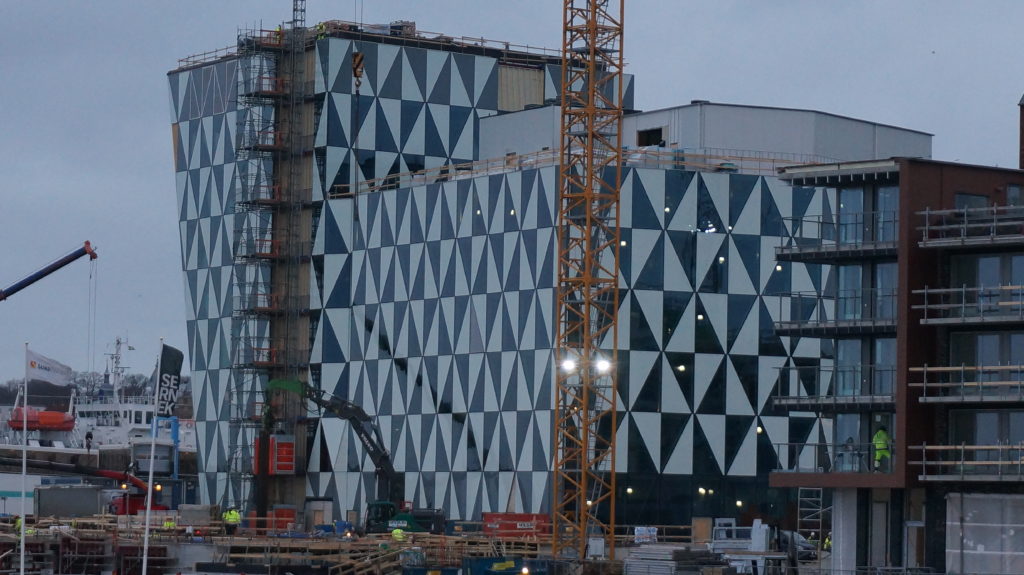
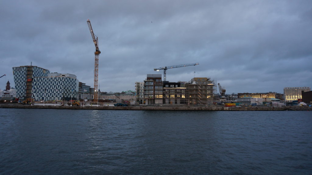
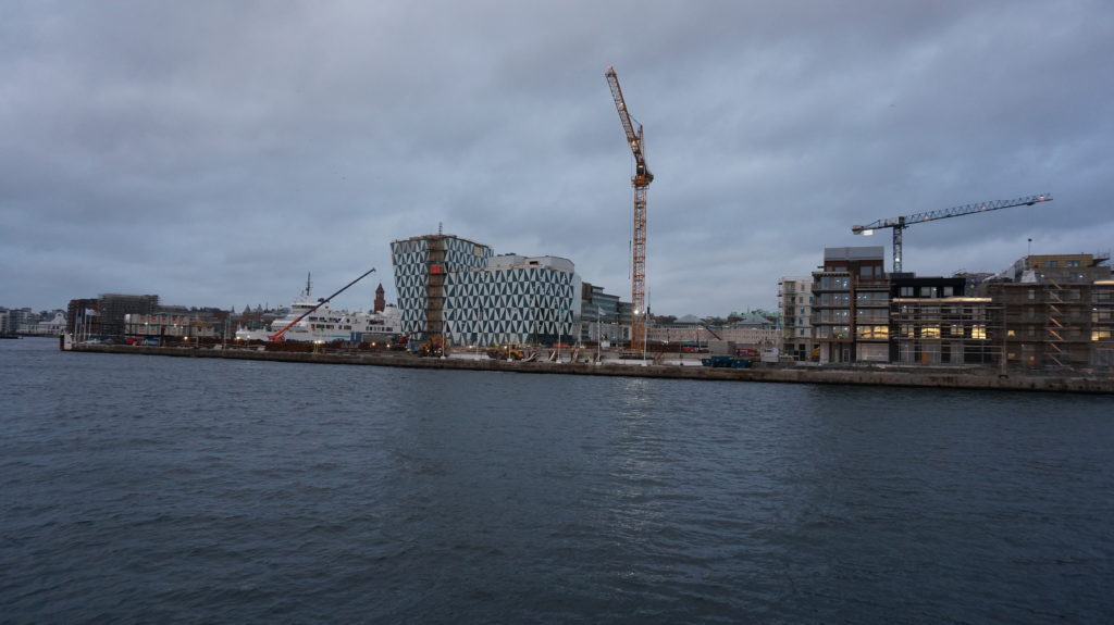
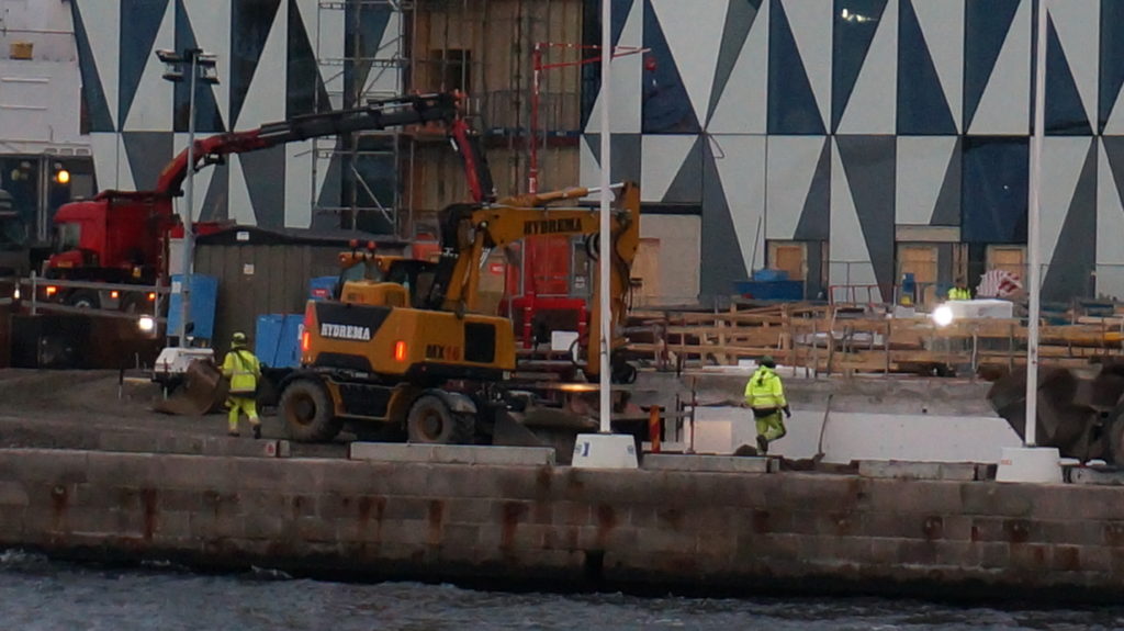
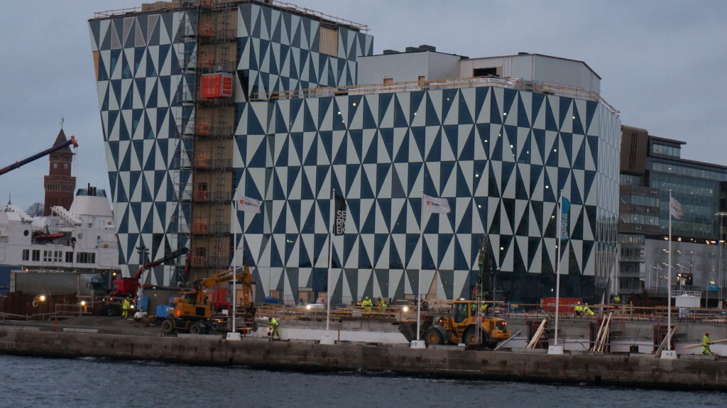
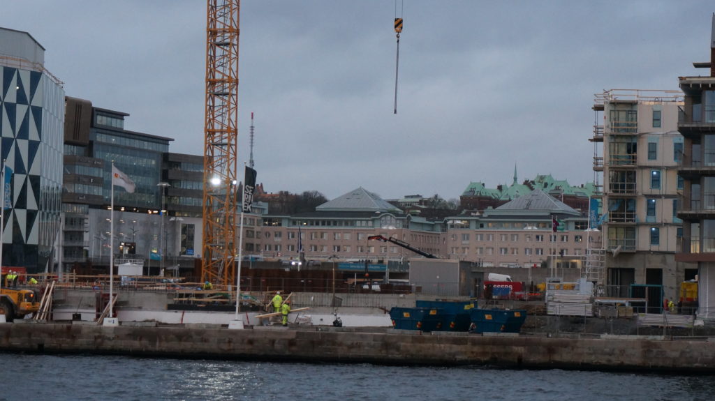
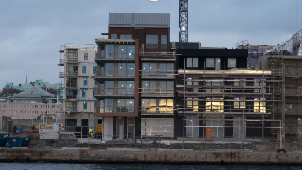
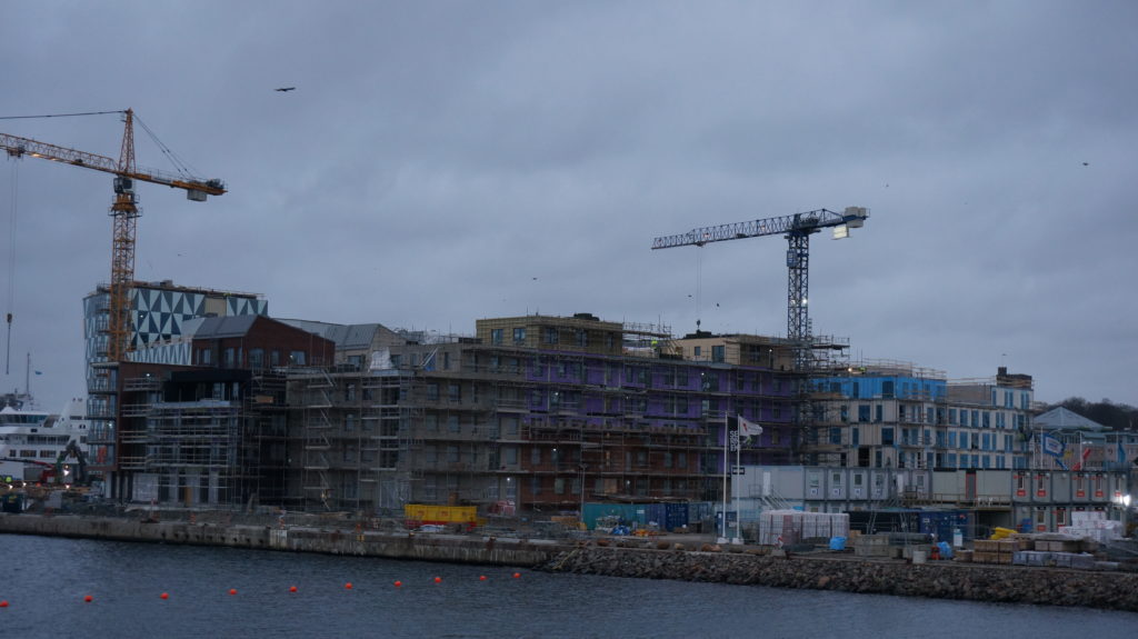
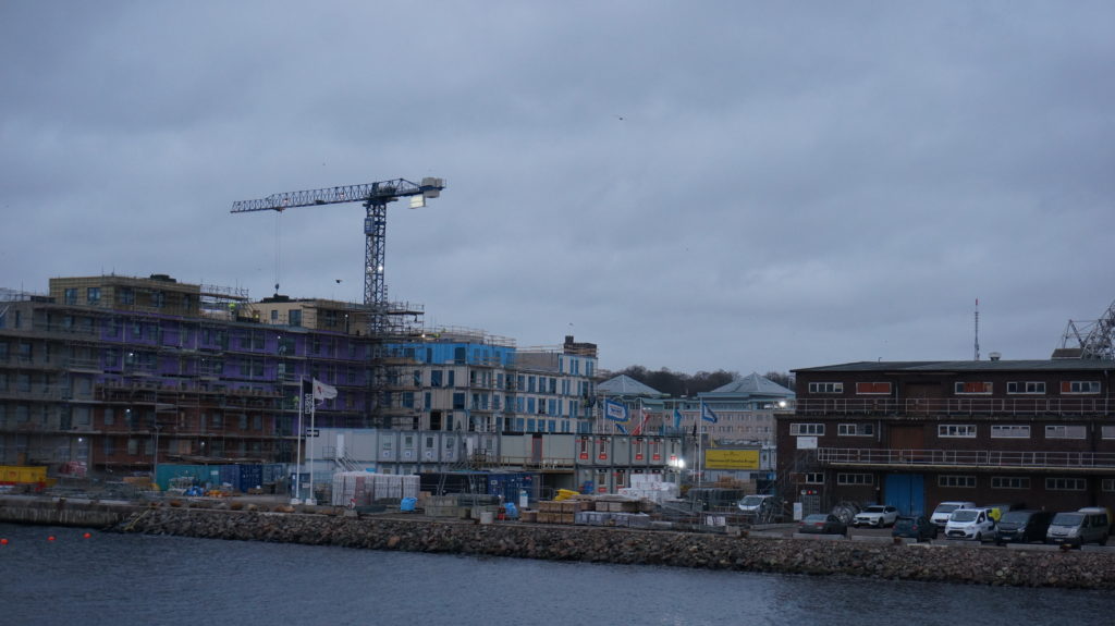
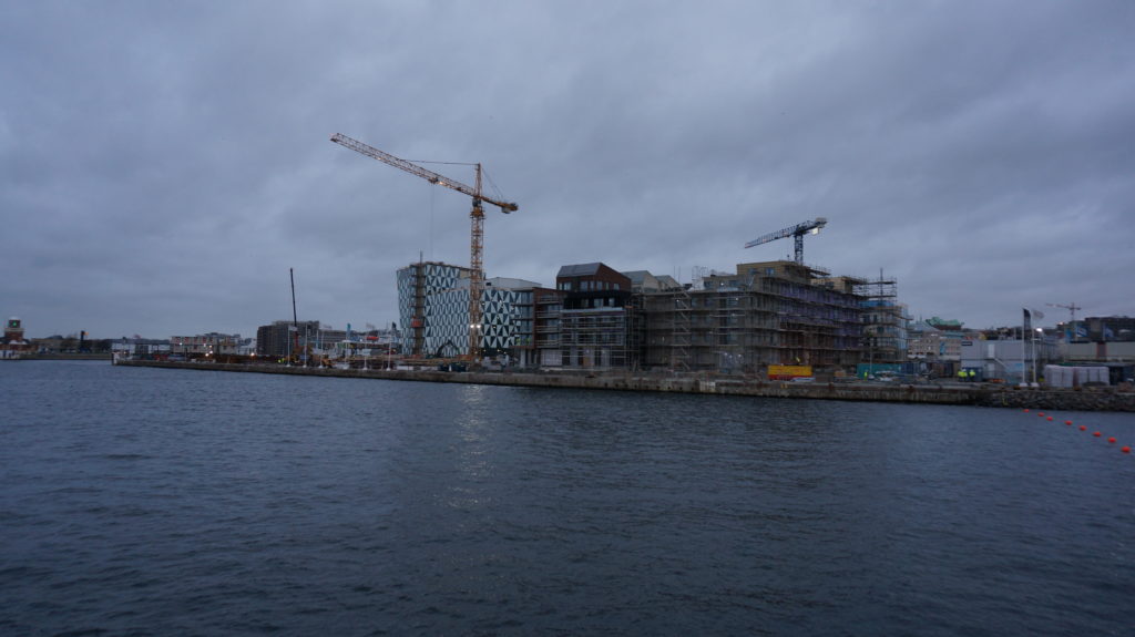
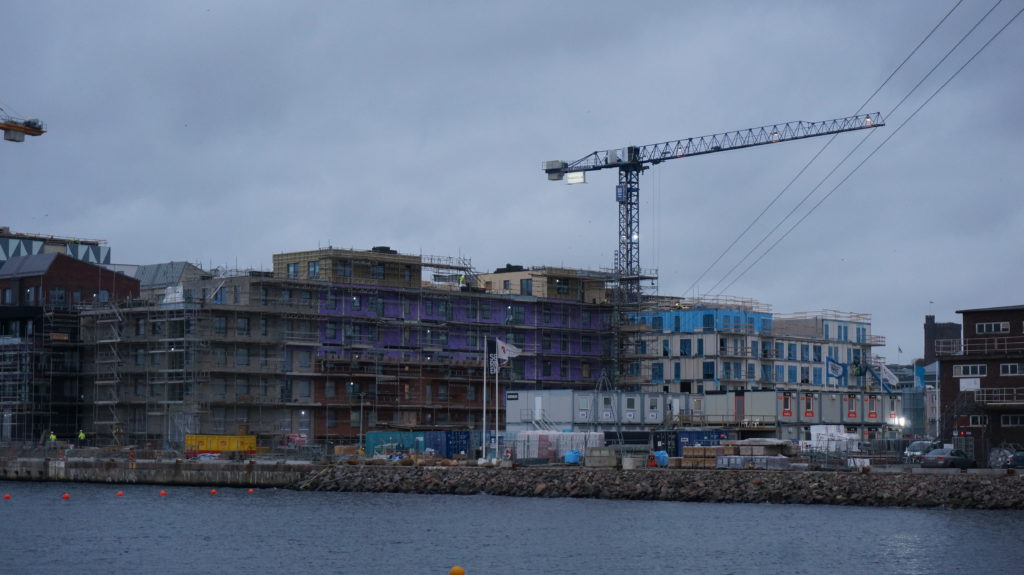
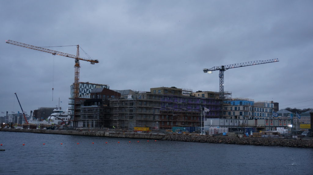
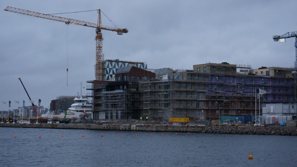
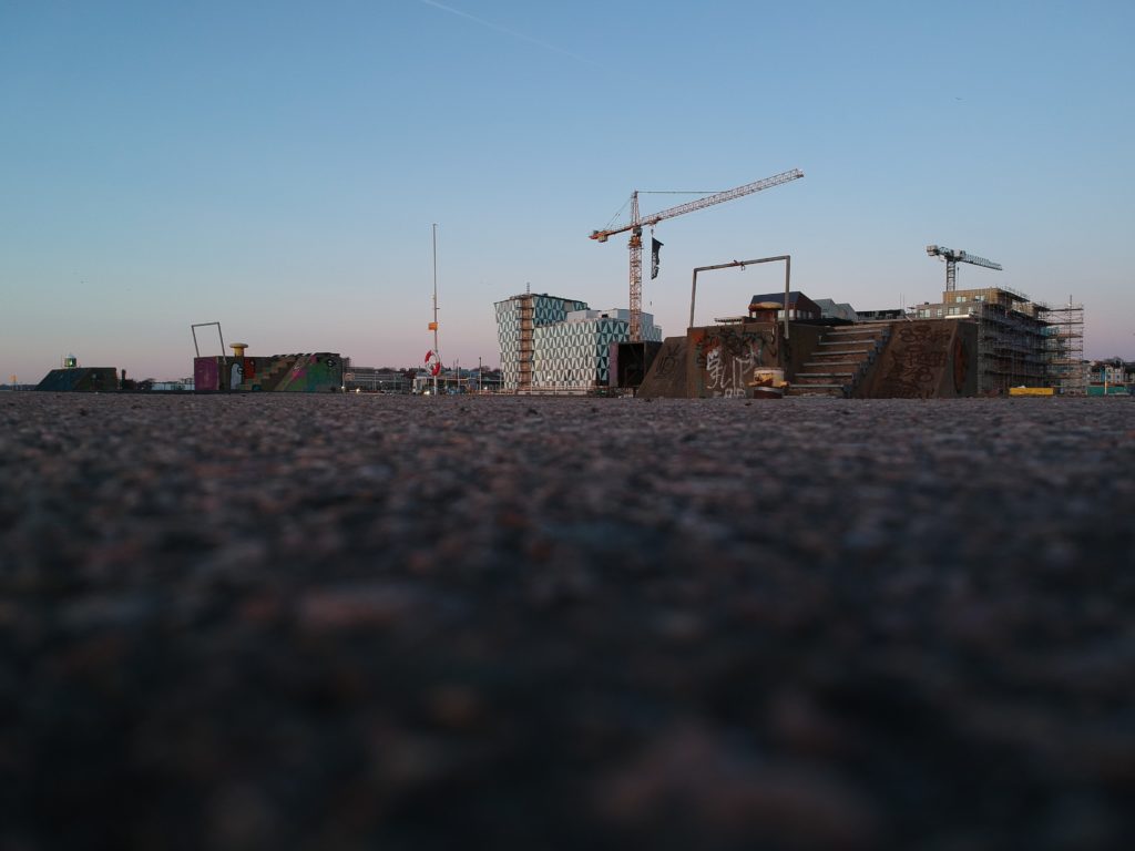
Oceanhamnsområdet är just nu en inhägnad byggarbetsplats där förvandlingen till en levande stadsdel med de första 450 bostäder pågår för fullt så att de första invånarna kan flytta in redan nästa år. Här byggs också restauranger, handelsyta och Oceanhamnen Waterfront Business District, ett nytt affärsdistrikt med 32 000 kvadratmeter nya kontor. Området får endast besökas av behörig personal med ID06 passerkort, så vi har inte möjlighet att gå dit och göra fältstudier på nära håll med eleverna. Så för att få en inblick i hur arbetsprocesserna och bygget fortskrider får vi ta till andra kreativa metoder. I första hand söker vi samarbeten med de aktörer som är inblandade i olika delar av Oceanhamnen-projektet.
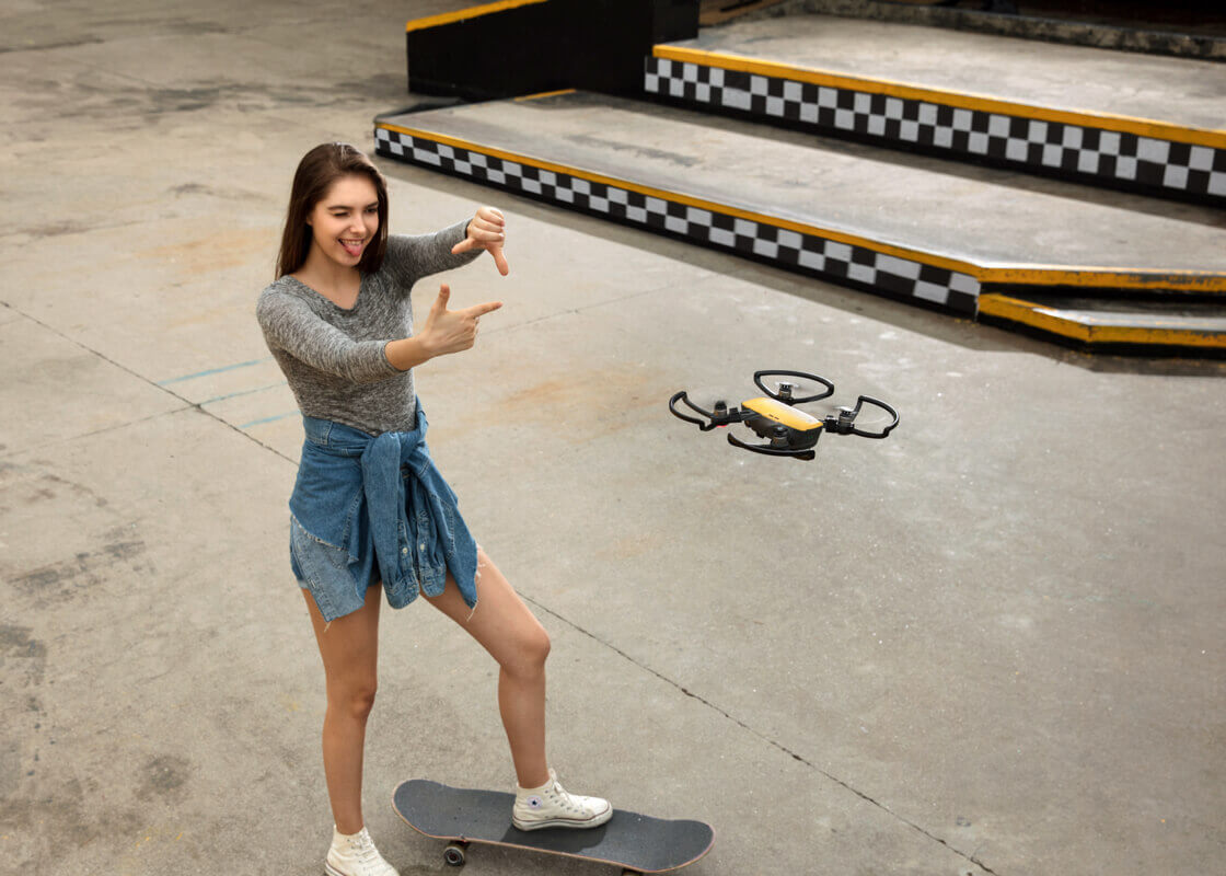
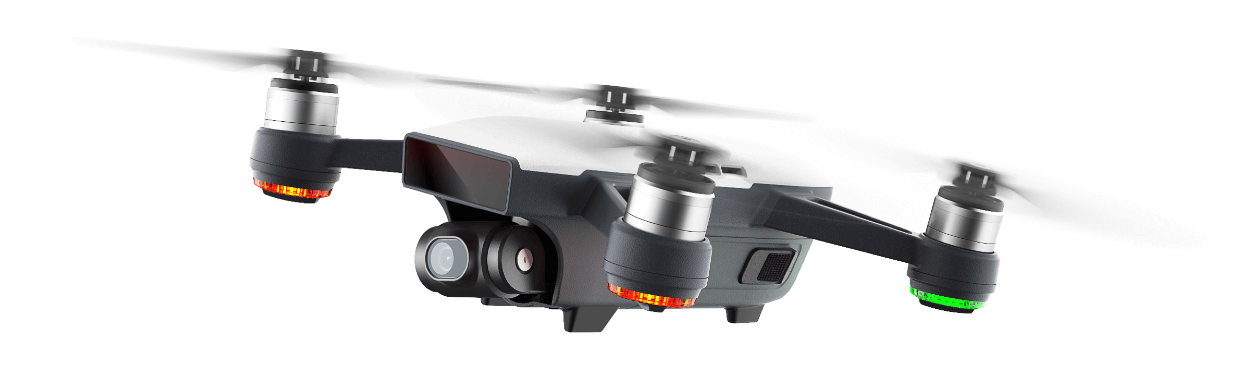
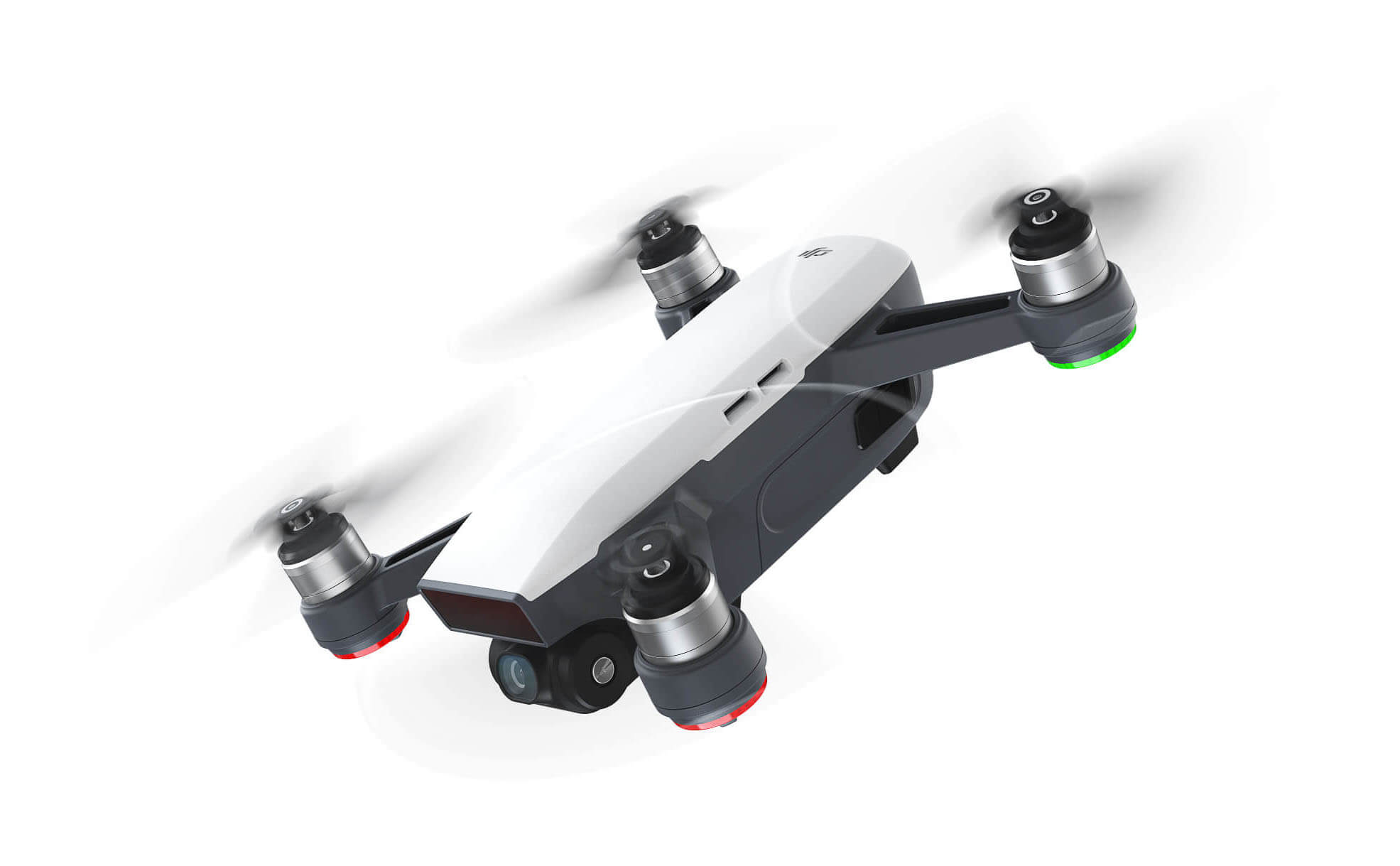
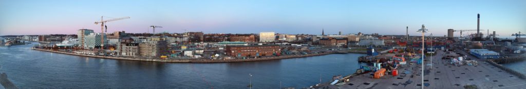
För att få lite perspektiv på projektet, fågelperspektiv alltså, så lyfte jag blicken och flög runt ett par varv och kollade in hur området ser ut idag, den 22 januari 2020.
Här nedan är ett litet filmklipp med en helikoptervy över området som vi kommer ha under luppen de närmaste månaderna.
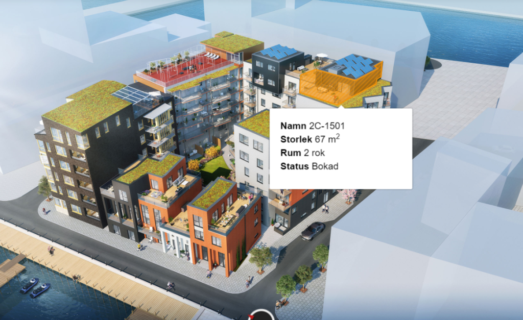
För att få en känsla för hur det är tänkt att se ut när Oceanhamnen är färdigbyggd så är en 3D-visualisering med realistisk rendering ett bra och kraftfullt verktyg. Här nedan får du en förhandstitt i 3D på den nya stadsdelen som håller på att växa fram med ett spektakulärt läge vid havet, ett stenkast från Helsingborgs centralstation. För att skapa en sådan film kan man t ex använda programvaran Blender 2.81 som vi börjat använda i kurserna Design, Konstruktion och Cad.
Digitalisering möjliggör nya innovativa arbetssätt
Om man vill gå ett steg längre och erbjuda en interaktiv upplevelse så att besökaren själv kan navigera runt i 3D-miljön så kan man istället lägga in de 3D-objekt man skapat i t ex Fusion 360 eller Sketchup, i spelutvecklingsmiljön Unity, som vi använt i undervisningen i Programmering. I Unity kan man även skapa en interaktiv VR- eller AR-upplevelse. Med Unity Reflect kan man sedan koppla samman konstruktionsritningarna och projektplaneringsverktygen och följa hela byggprocessens alla olika steg i VR från en annan plats, eller med hjälp av AR-teknik se hur byggnaden steg för steg kommer att byggas upp precis där du står, trots att det ännu inte är klart. Det är som att i realtid kunna se in i framtiden, in genom väggar eller tillbaka till hur någonting såg ut innan.
Här kan du se var byggherrarna bygger
Det är totalt sex byggherrar som ska bygga bostäder i den nya stadsdelen. Vi vill gärna samarbeta med dem på olika sätt inom ramen för de kurser eleverna läser, men även för SYV (Studie- och Yrkes-Vägledning). Det kan t ex handla om studiebesök, intervjuer, designuppdrag eller praktikplatser.
Kartan härunder visar var de ska bygga, och länkarna går till mer information om dem och deras projekt.

- 1A-B – Midroc Property Development
- 2A – Sundprojekt
- 2B – Serneke
- 3A – Serneke
- 3B – Riksbyggen
- 4A-B Magnolia
Vid havet, mitt i centrum
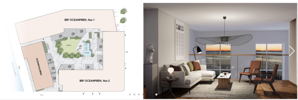
Oceanpiren är en del av Oceanhamnen, ett nytt spännande bostadsområde mitt i Helsingborg. På bästa läge, längst ut på piren, bygger vi 69 bostadsrätter om 1-4 RoK – Brf Oceanpiren. Här bor du på första parkett vid havet, i hjärtat av stadsdelen, i ljusa, välplanerade bostadsrätter som är byggda för en hållbar livsstil. Samtidigt om vi uppför Brf Oceanpiren bygger vi fyra radhus i townhouse-stil. Vi kallar dem Oceanvillorna. De har både hållbarhetstänket och den magnifika havsutsikten gemensamt med Brf Oceanpiren.

För mer information om Brf Oceanpiren se oceanpiren.se, den interaktiva presentationssidan för de olika bostadsobjekten eller de två faktabladen (pdf) för hus 1 och hus 2.
Design-, konstruktions- och CAD-uppgifter till TE18DP
Här är en lista på exempel på arbeten och uppdrag som eleverna ska jobba med. Mer utförliga och detaljerande instruktioner ges under lektionerna, men de olika uppgifterna publiceras också på sidorna Designuppgifter för TE18DP och Konstruktions- och CAD-uppgifter för TE18DP.
- Skapa en CAD-ritning på en av lägenheterna i Brf Oceanpiren. Utgå från planritningen.
- Skapa ett komplett inredningsförslag till lägenheten.
- Skapa konstruktionsritningar av väggsektioner, tak och golv i minst två olika material.
- Skapa en materiallista och kostnadskalkyl för de ingående konstruktionselementen.
- Gör hållfasthetsberäkningar och riskanalyser
- Jämför materialalternativen med hänsyn till kostnad, hållfasthet, hållbarhet, miljöpåverkan, klimatavtryck och möjlighet till återvinning (livscykelanalys).
Oceanvillorna
https://public.wec360.se/midroc/oceanhamnen/a-1003/index.html
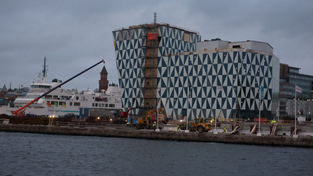
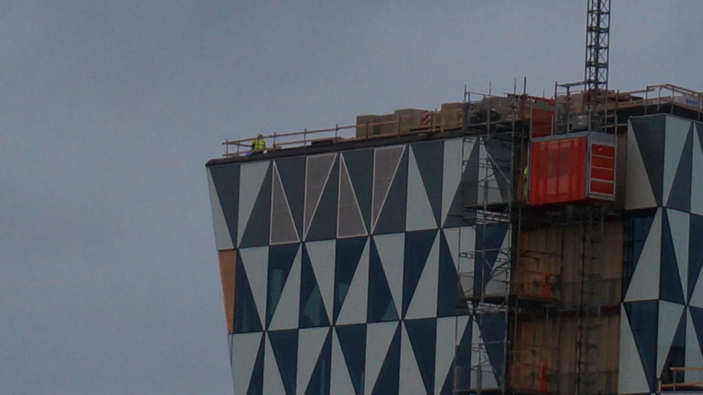
World Trade Center Helsingborg
World Trade Center Helsingborg i Oceanhamnen ska bli mötesplatsen för entreprenörer, scale-ups, etablerade företag och affärs- och helgresenärer.
![MP_kontor_99493_WTC Oceanhamnen_Bröderna Pihls gränd_västerbild ([3149][@[resize:5200,2930][crop:34,0,5021,2919][autoorient:][background:%23ffffff][quality:80][strip:][extension:jpg][id:7]]).jpg](https://www.wtcmalmolundhelsingborg.se/siteassets/qbank/mp_kontor_99493_wtc-oceanhamnen_broderna-pihls-grand_vasterbild-3149resize52002930crop34050212919autoorientbackground23ffffffquality80stripextensionjpgid7.jpg?width=1010&height=630&scale=both&mode=crop)
WTC Helsingborg blir en kontors- och hotellfastighet som kommer bli ett landmärke i Helsingborg. Med sina fjorton våningar precis vid hamninloppet ger den dig närkontakt med sundet, båtarna och kontinenten. Här kommer finnas gemensam service som reception och konferensavdelning. Gym, relax, dusch- och omklädningsrum. Restaurangen med uteservering vid vattnet och takterasser är ytterligare fördelar som berikar både arbets- och privatliv. I källaren planeras för cykelgarage med möjligheter till reparationer och en laddstation för elcyklar.
Fastighet är ritad av Juul Frost Arkitekter, men byggherren Midroc välkomnar kunderna tidigt in i processen för att kunna påverka lokalens utformning så att den passar verksamheten bäst. Att vara med och arbeta med förslag på lokalernas utformning kan vara ett bra elevprojekt!
Juul Frost Arkitekter är förövrigt experter på design av campusområden och studentbostäder, och hur man kan integrera dem i städer.
Läs mer om World Trade Center Helsingborg på följande länkar:
https://www.midroc.se/fastighetsutveckling/ny-lokal/nybyggnadsprojekt-lokaler/helsingborg-world-trade-center/
Se en typskiss på en kontorslokal i WTC:
https://www.wtcmalmolundhelsingborg.se/globalassets/lime/documents/483701-pdf-document.pdf
Oceanhamnen får ett innovativt nytt avloppssystem – Reco Lab med Tre Rör Ut
Oceanhamnen kommer få en helt ny typ av klimatsmart avloppssystem med värmeåtervinning och lokalt producerad biogas. Varje fastighet ansluts till tre separata rör, ett för matavfall, ett för gråvatten och ett för svartvatten. Detta innovativa avloppssystem kräver att ingenjörerna tänker utanför boxen. I filmklippet ovan berättar VA-ingenjören Peter Winblad på Nordvästra Skånes vatten och avlopp, NSVA, om utmaningarna.
Reco Lab – en testbädd och showroom för framtidens källsorterande avloppssystem
Reco Lab kommer att bidra till att utveckla det världsunika systemet Tre Rör Ut för insamling och hantering av mat- och toalettavfall i fastigheterna på Oceanpiren i stadsdelen Oceanhamnen i centrala Helsingborg.
På uppdrag av NSVA har entreprenörföretaget NCC upphandlat det nederländska företaget Landustrie och det svenska företaget EkoBalans Fenix AB för att installera processteg i det unika Reco labs utvecklingsanläggning. Reco lab, som är en del av Öresundsverket i Helsingborg, ska behandla det källsorterade avloppet från Helsingborgs nya stadsdel, Oceanhamnen. Avloppshantering har en naturlig roll att spela i den cirkulära ekonomin då mycket av våra essentiella resurser, som vatten, näringsämnen och organiskt material passerar igenom stadens avlopp.
Det källsorterande avloppet innebär en reningsprocess med kraftigt ökad resursåtervinning. Miljövinsterna är flera:
- ökad biogasproduktion
- ökad näringsåtervinning
- effektiv värmeåtervinning
- mer energieffektiv läkemedelsrening
- minskad klimatpåverkan
- möjligheten för vattenåtervinning
Reco Lab planeras att vara färdigbyggt och driftsatt våren 2021 och inkluderar även ett showroom för utbildning samt en testbädd för teknikutveckling.
Studiebesök hos NSVA för natureleverna (NA19) är planerat till maj 2020.
Eleverna i NA18 borde också studera Reco Lab som en del av biologi- och kemikurserna, i synnerhet de som valt inriktningen mot natur och samhälle.
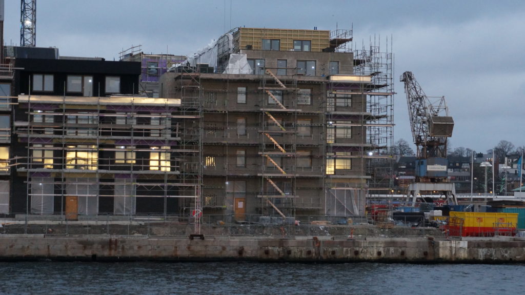
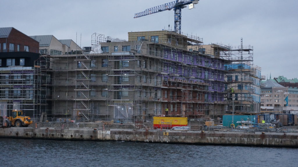
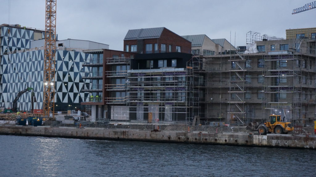
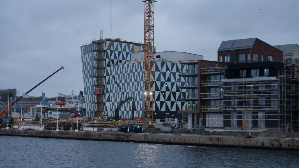
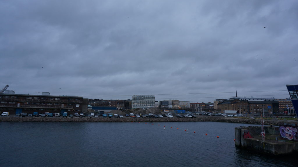
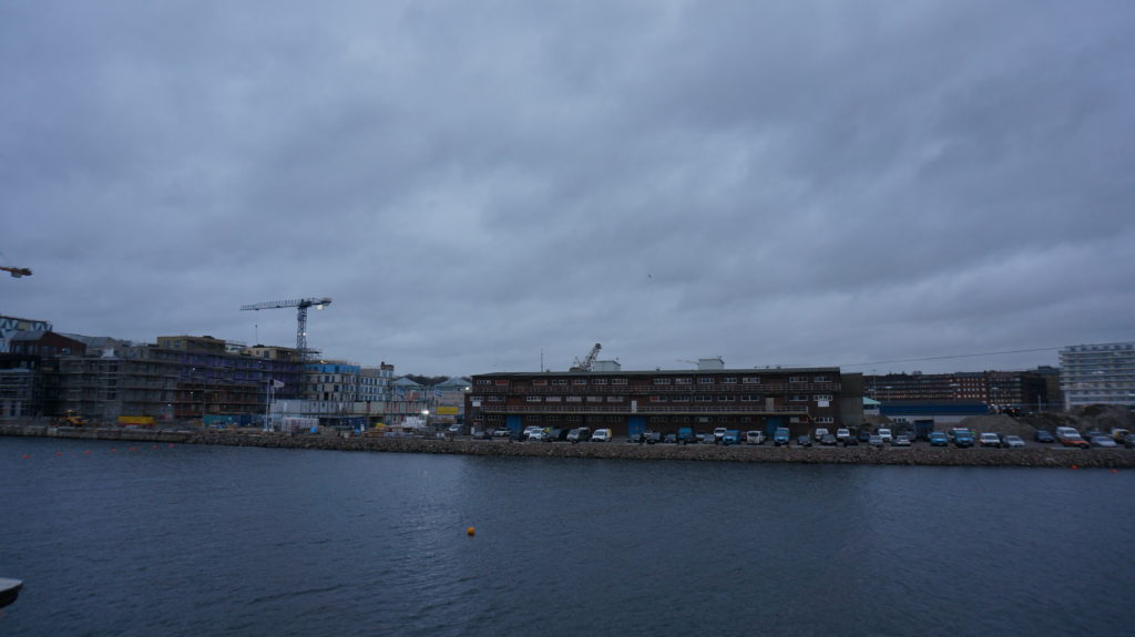
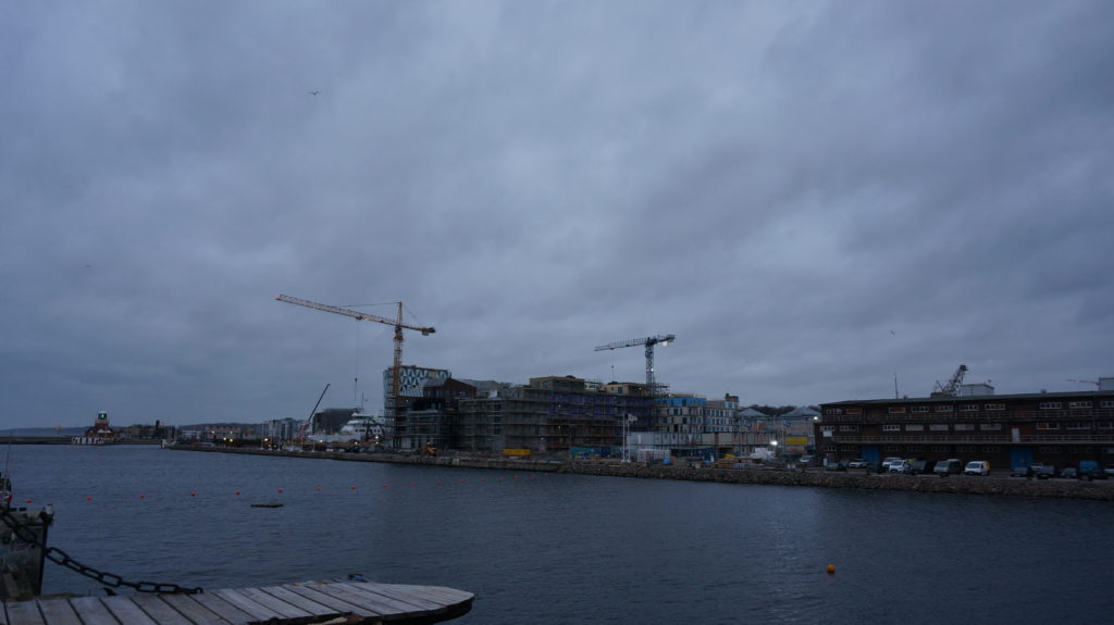
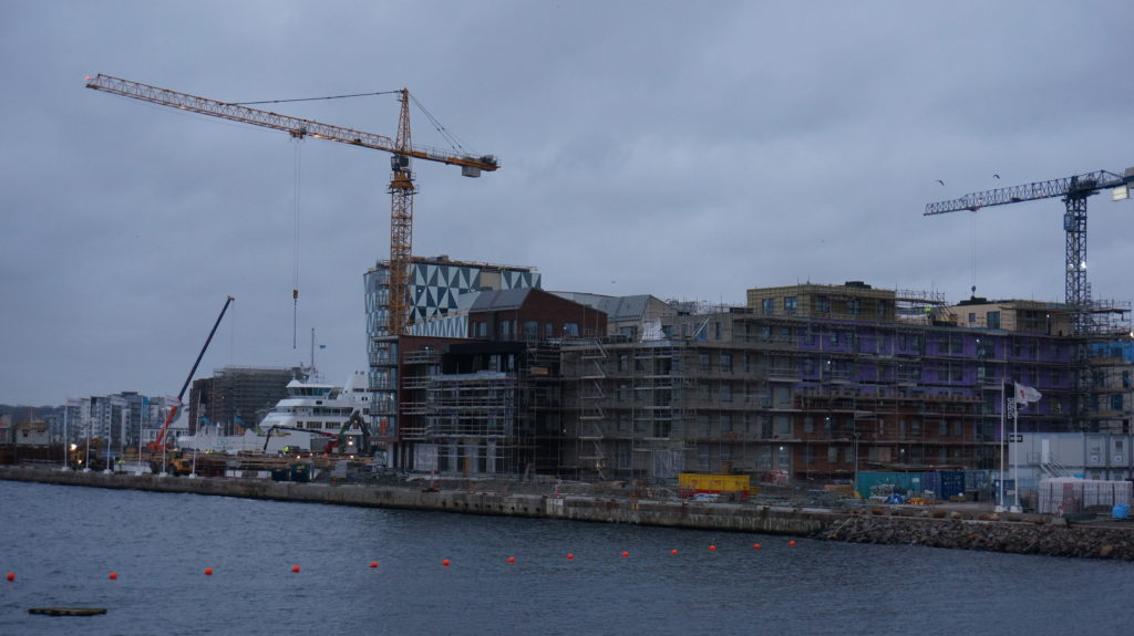
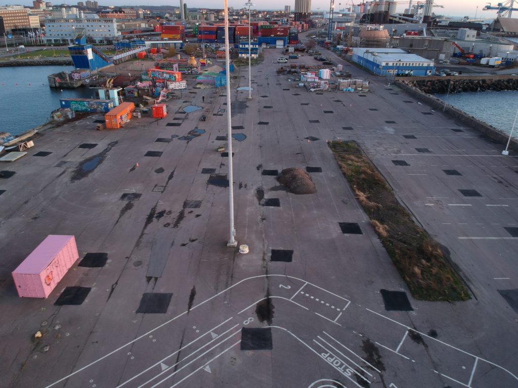
Bilder på bygget av Oceanhamnen
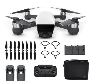
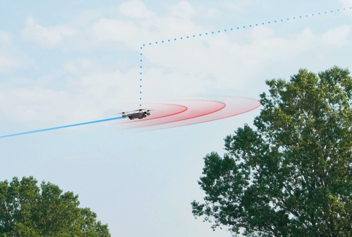
Bilder från fältstudie vid Oceanhamnen och Pixlapiren 2020-01-22 med drönaren DJI Spark:
DCIM/100MEDIA/DJI_0307.JPG 
DCIM/100MEDIA/DJI_0309.JPG 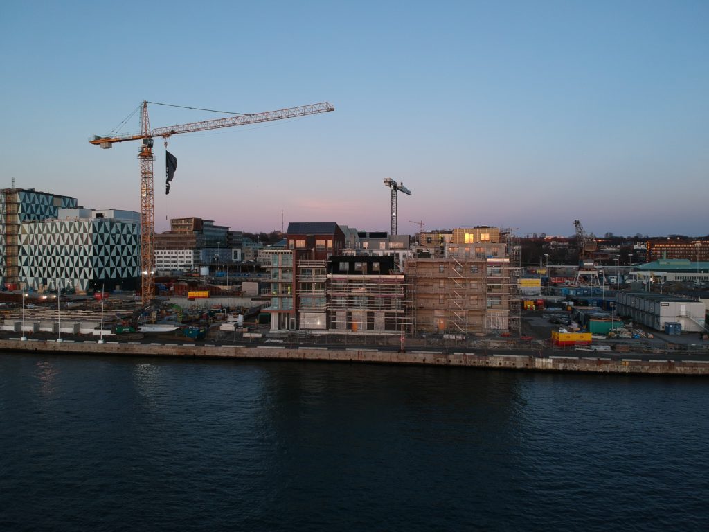
DCIM/100MEDIA/DJI_0310.JPG 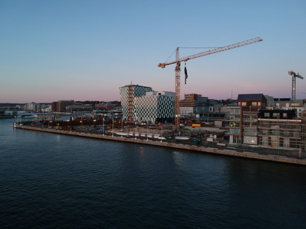
DCIM/100MEDIA/DJI_0311.JPG 
DCIM/100MEDIA/DJI_0312.JPG 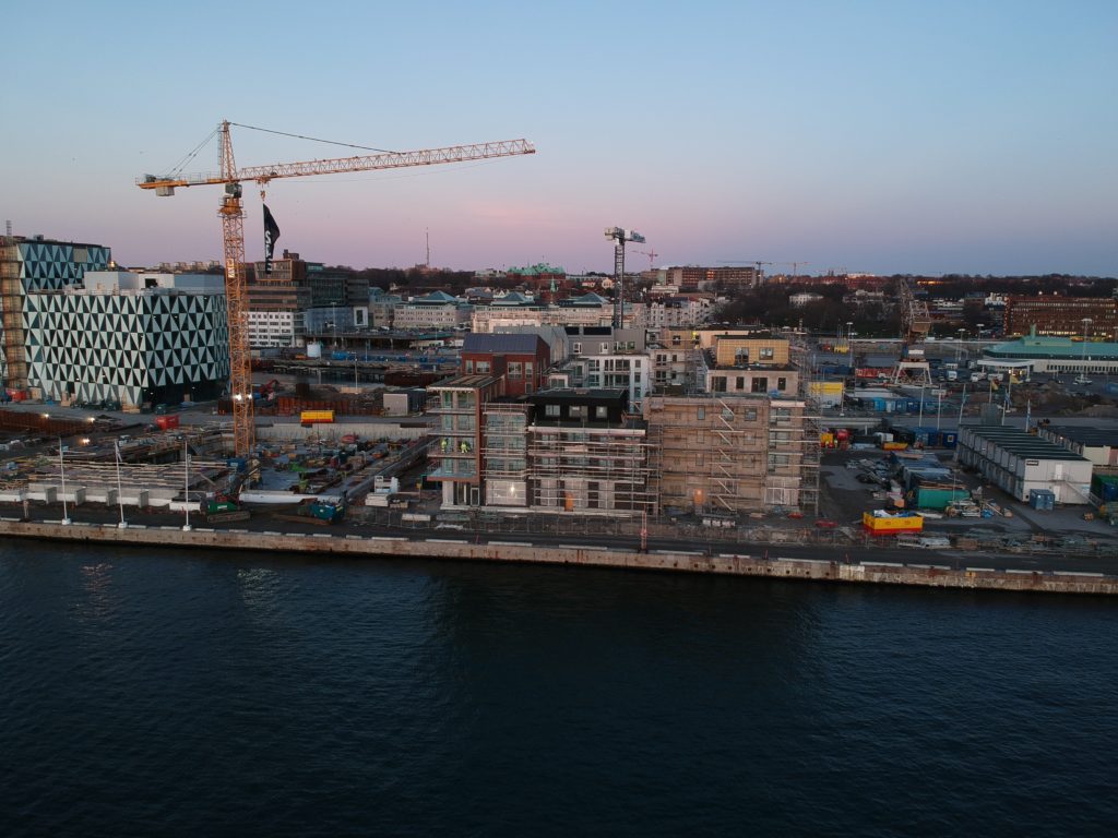
DCIM/100MEDIA/DJI_0314.JPG 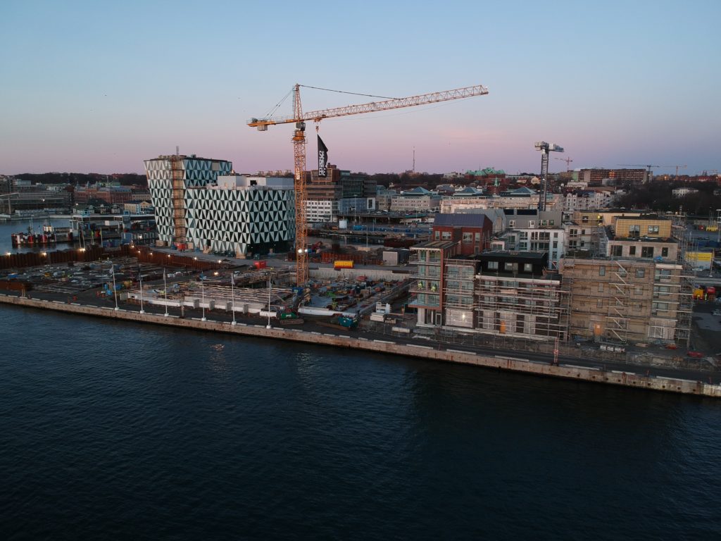
DCIM/100MEDIA/DJI_0315.JPG 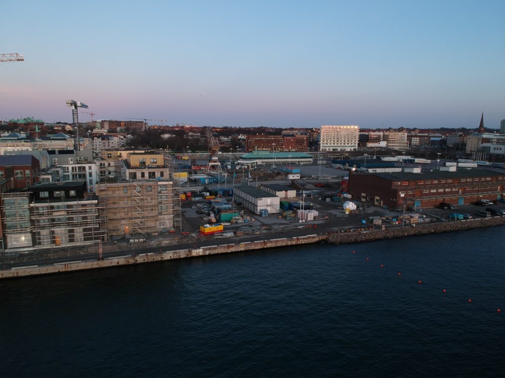
DCIM/100MEDIA/DJI_0316.JPG 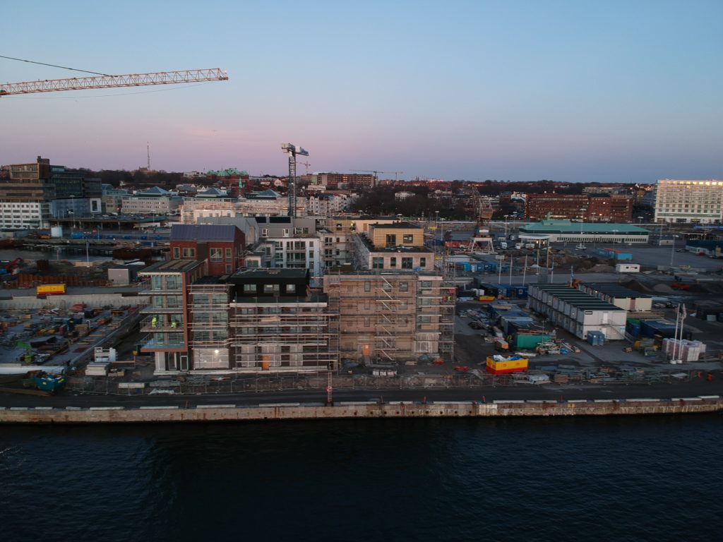
DCIM/100MEDIA/DJI_0317.JPG 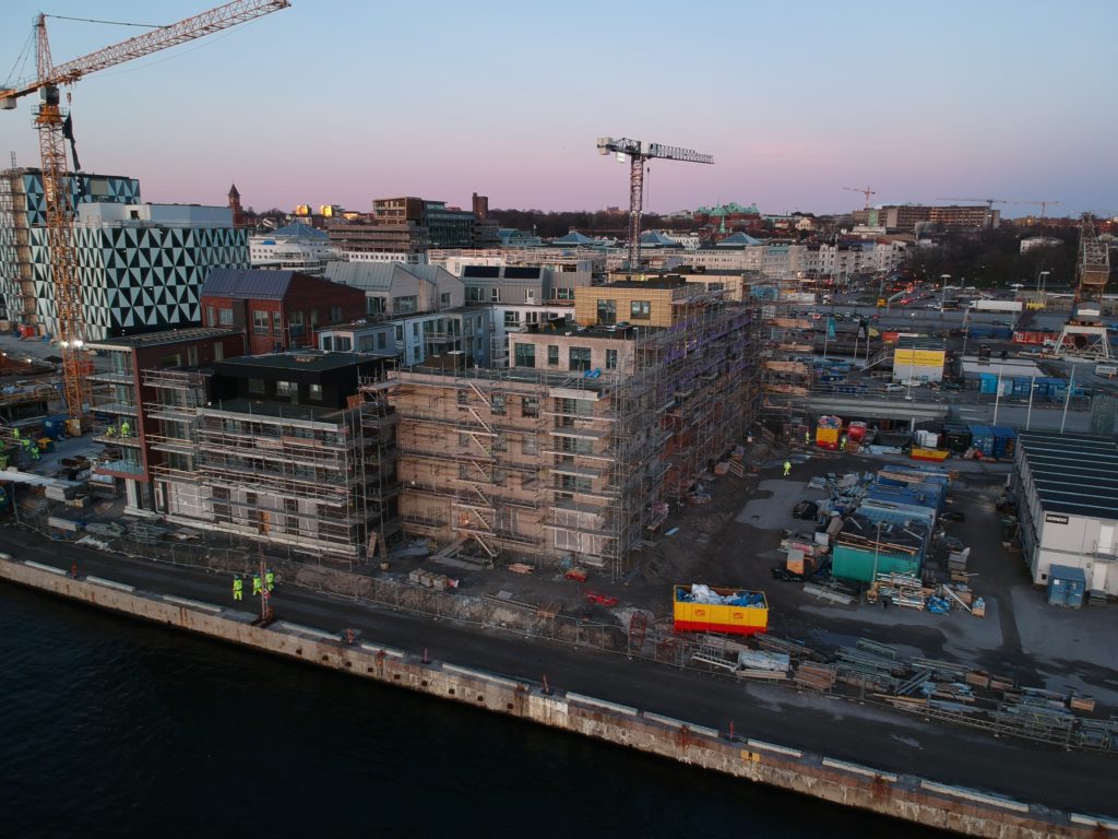
DCIM/100MEDIA/DJI_0319.JPG 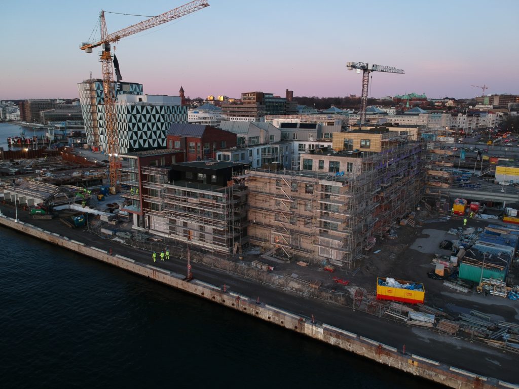
DCIM/100MEDIA/DJI_0320.JPG 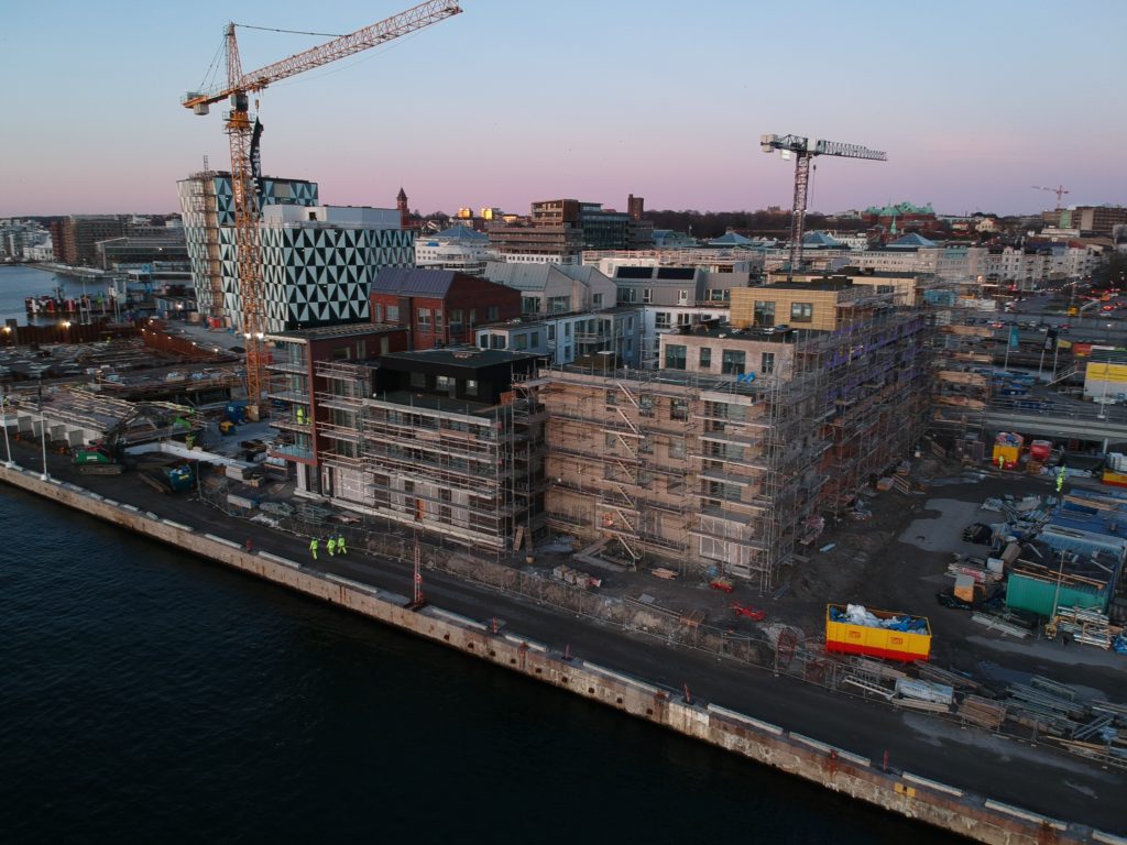
DCIM/100MEDIA/DJI_0321.JPG 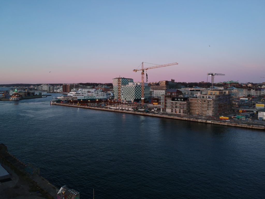
DCIM/100MEDIA/DJI_0323.JPG 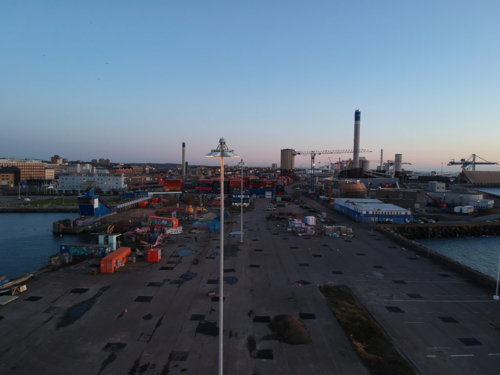
DCIM/100MEDIA/DJI_0325.JPG 
DCIM/100MEDIA/DJI_0326.JPG 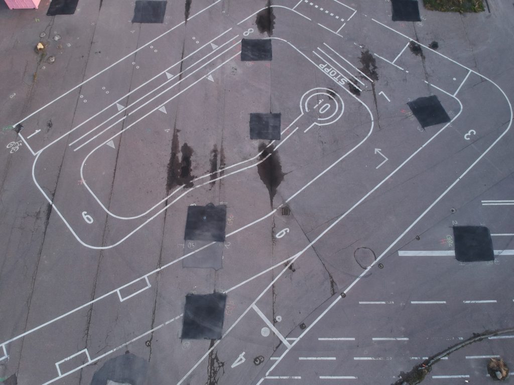
DCIM/100MEDIA/DJI_0327.JPG 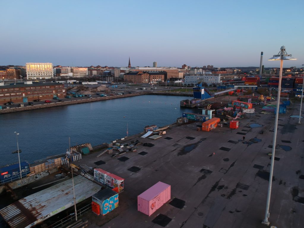
DCIM/100MEDIA/DJI_0328.JPG 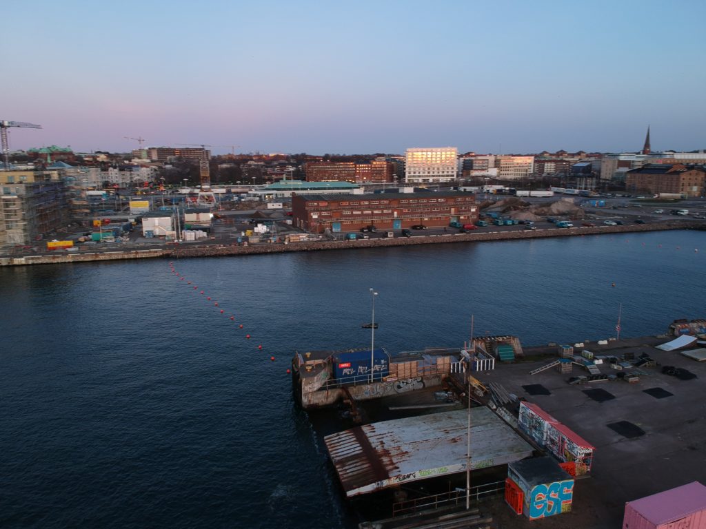
DCIM/100MEDIA/DJI_0329.JPG 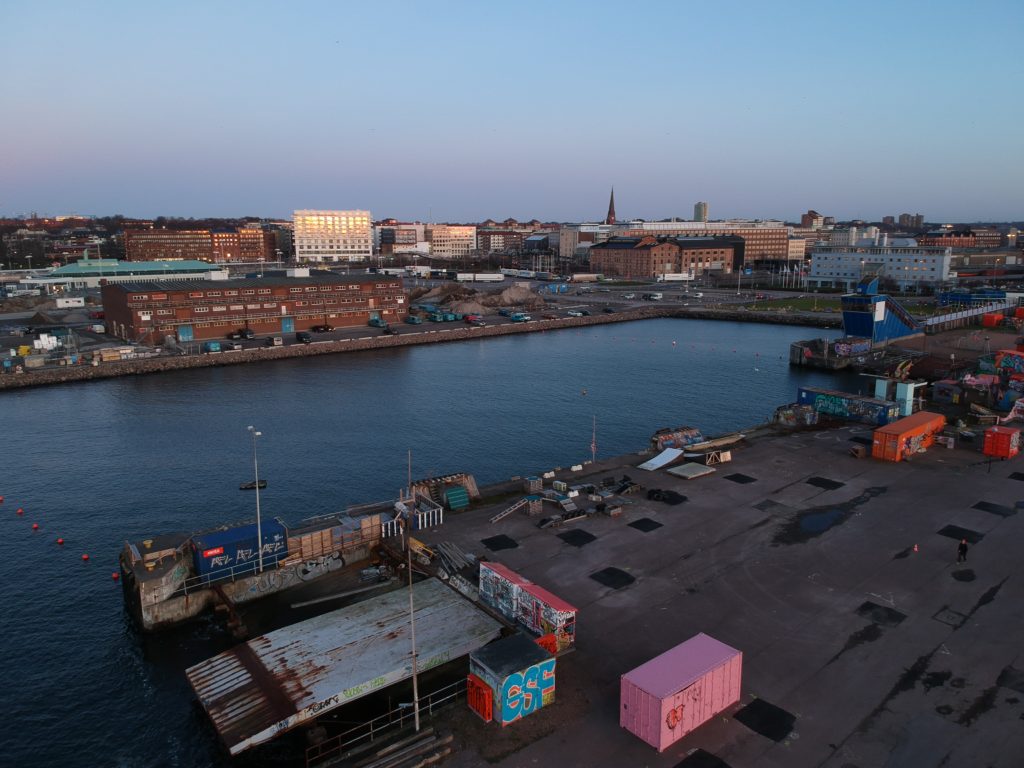
DCIM/100MEDIA/DJI_0330.JPG 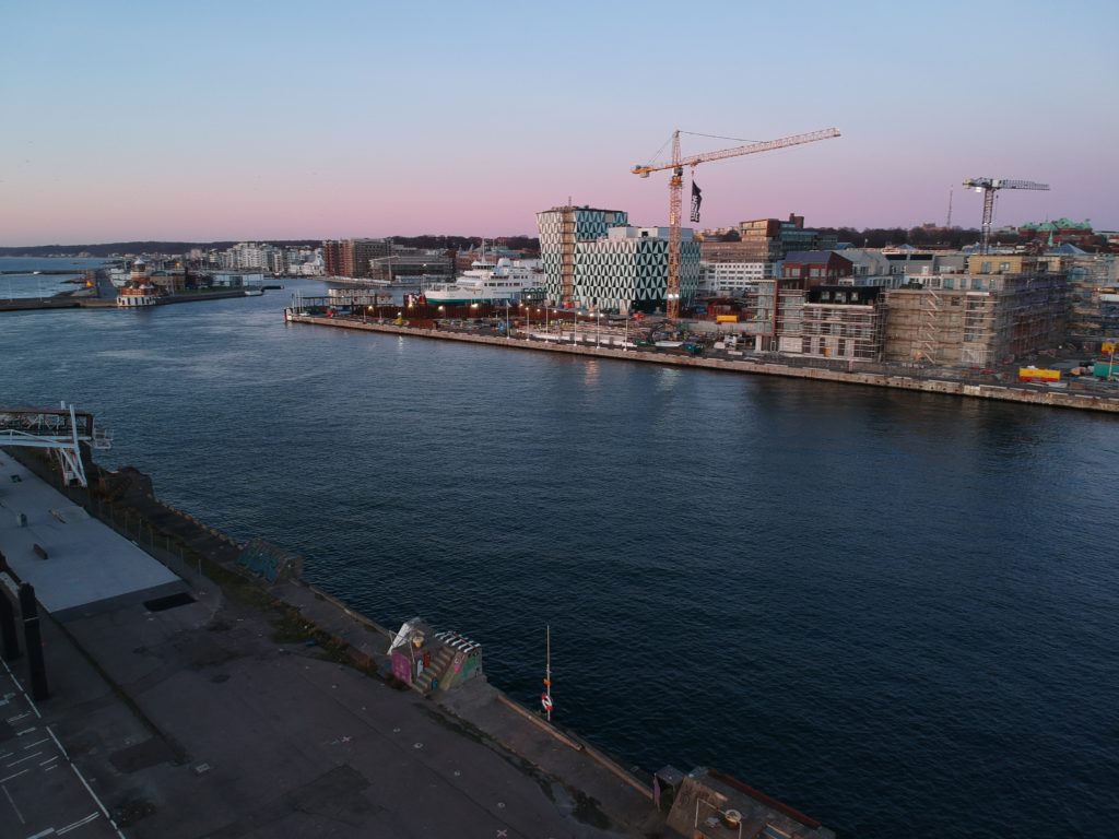
DCIM/100MEDIA/DJI_0331.JPG 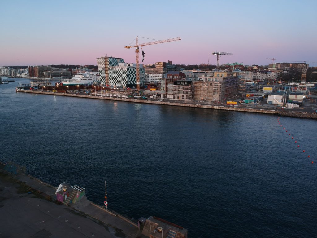
DCIM/100MEDIA/DJI_0332.JPG 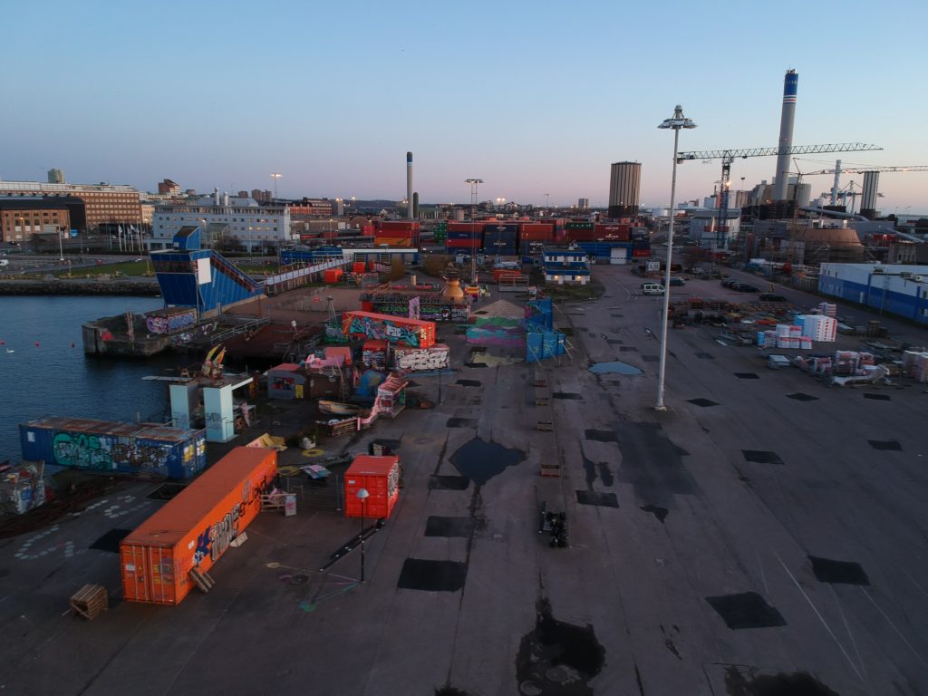
DCIM/100MEDIA/DJI_0334.JPG 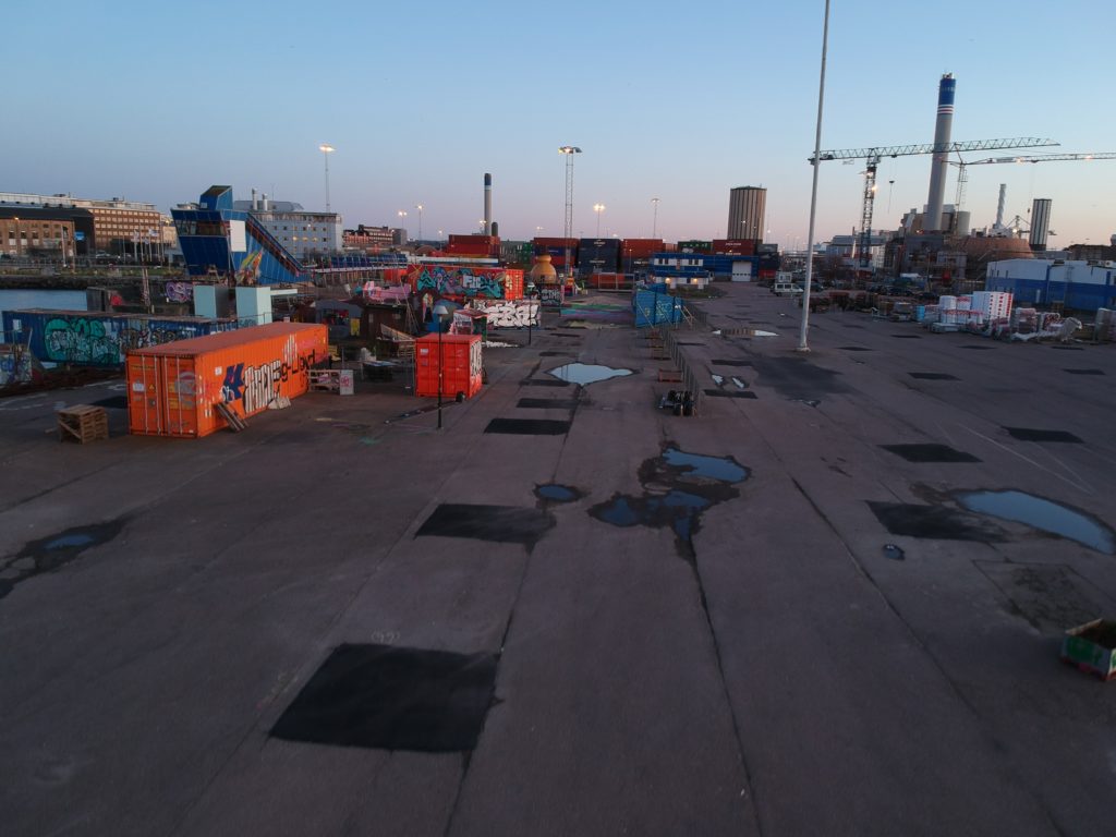
DCIM/100MEDIA/DJI_0335.JPG 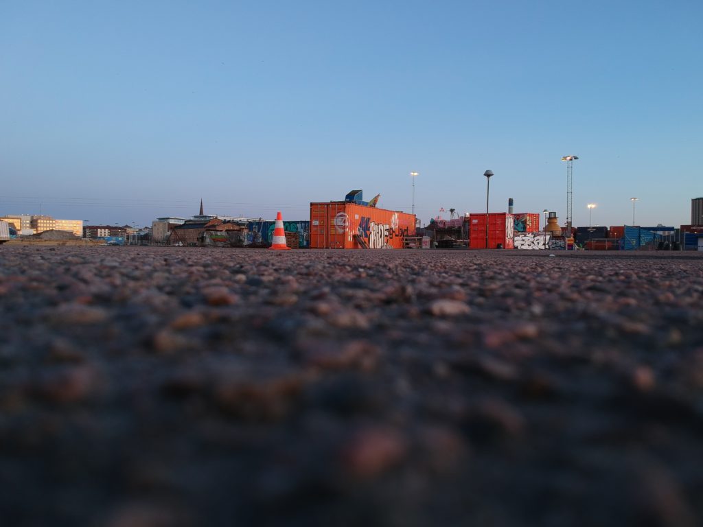
DCIM/100MEDIA/DJI_0336.JPG 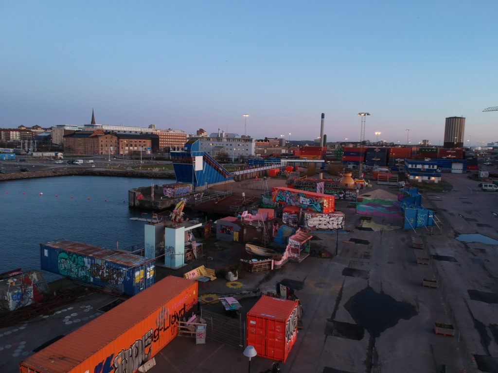
DCIM/100MEDIA/DJI_0338.JPG 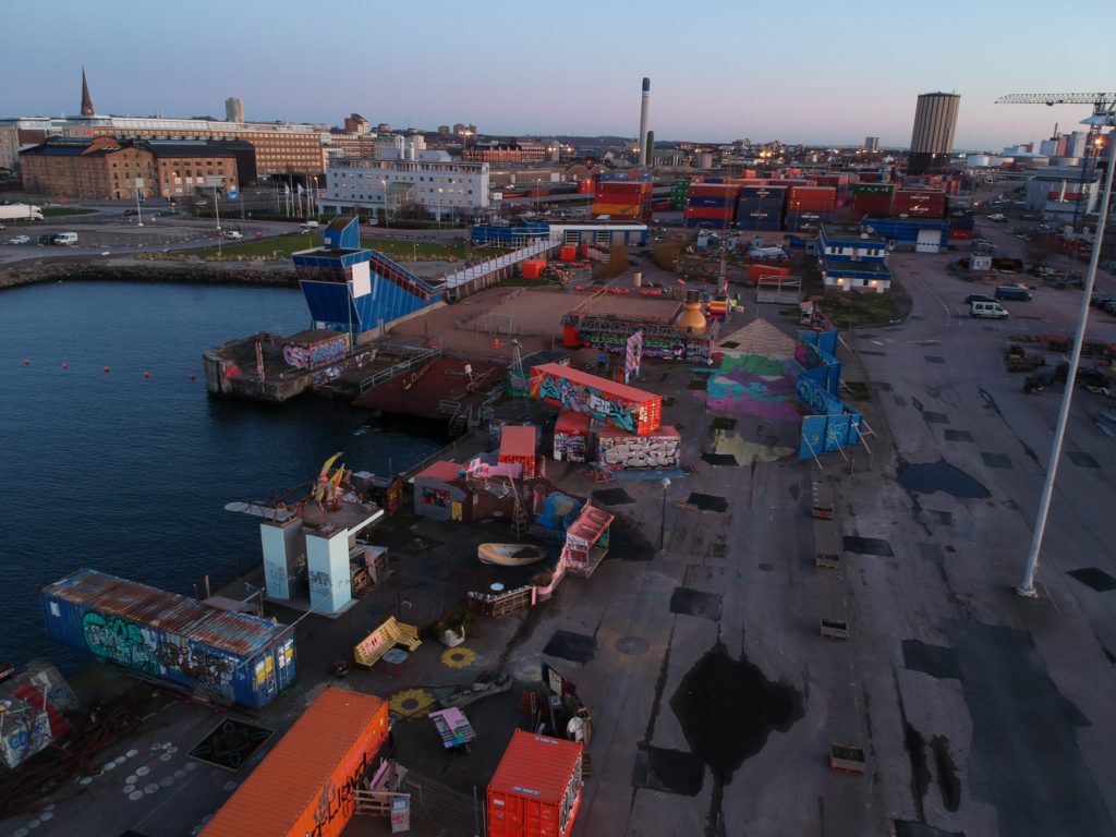
DCIM/100MEDIA/DJI_0339.JPG 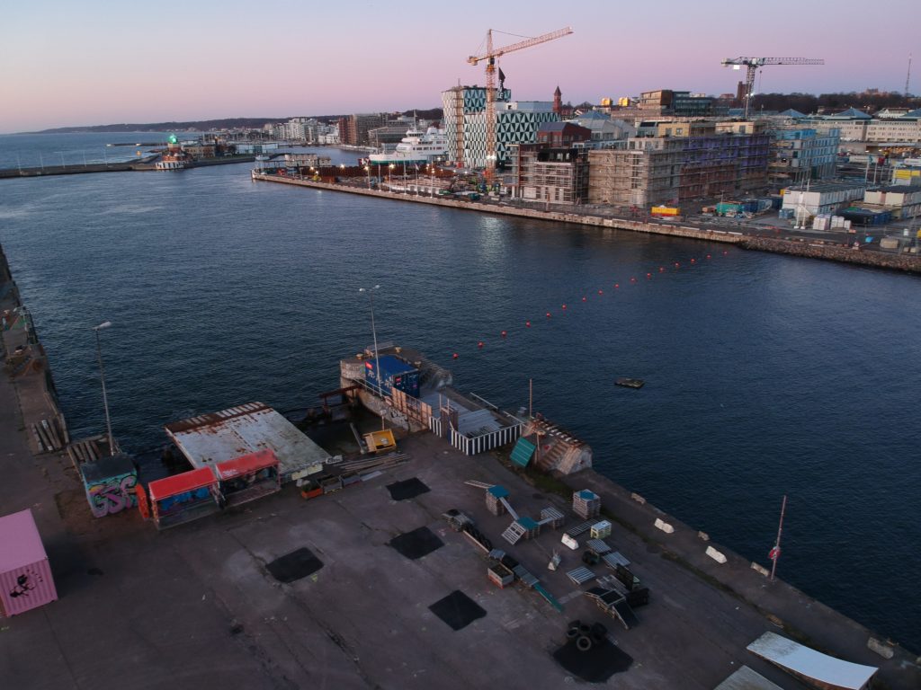
DCIM/100MEDIA/DJI_0340.JPG 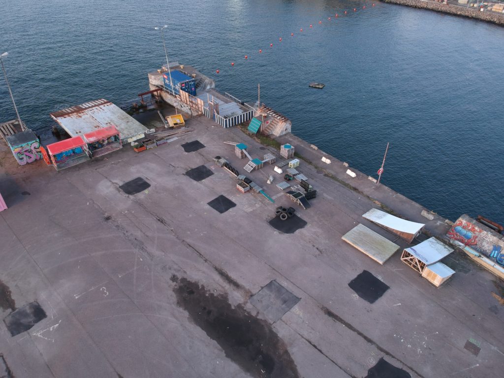
DCIM/100MEDIA/DJI_0342.JPG 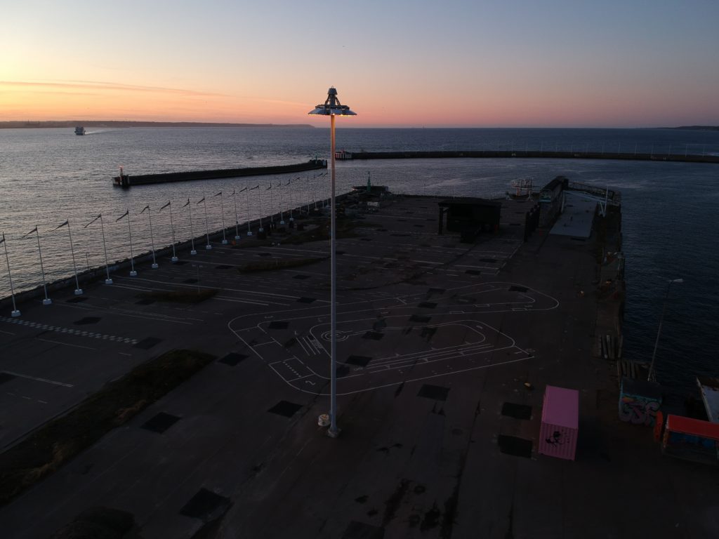
DCIM/100MEDIA/DJI_0343.JPG 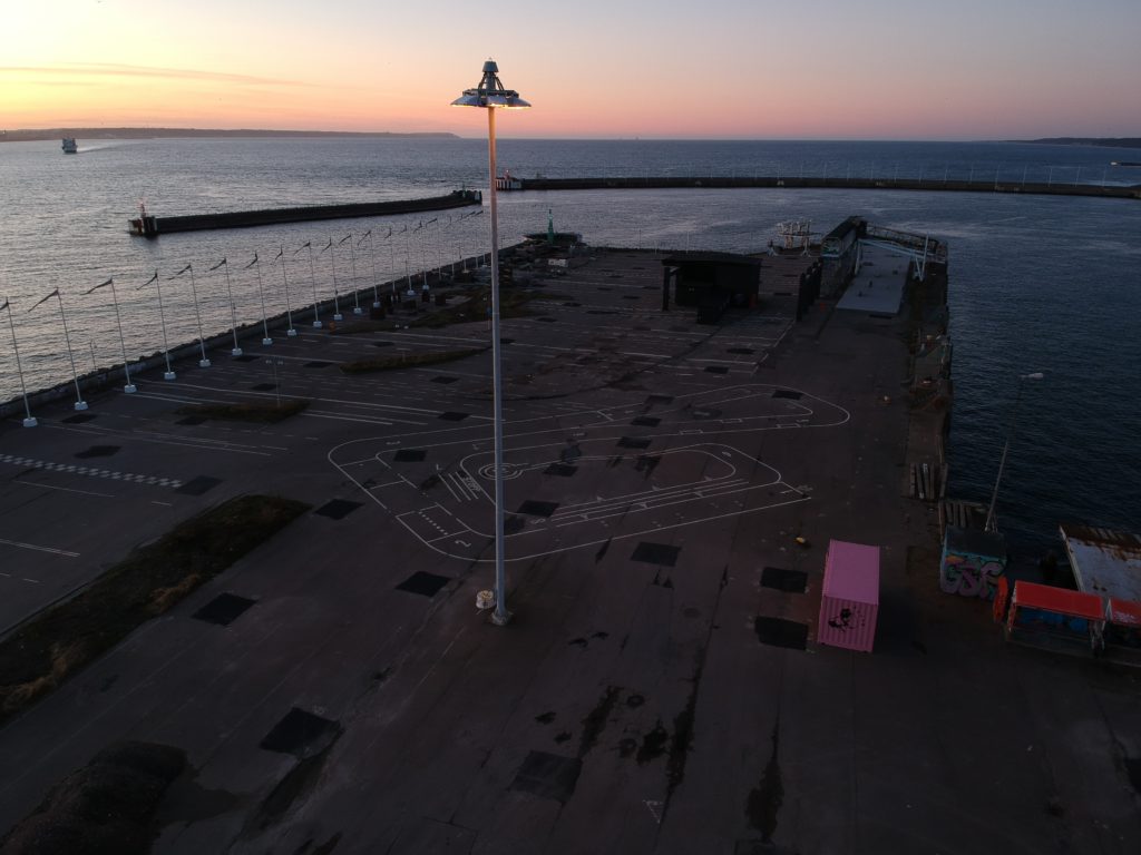
DCIM/100MEDIA/DJI_0344.JPG 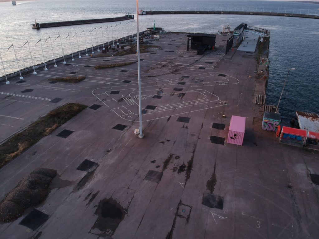
DCIM/100MEDIA/DJI_0345.JPG 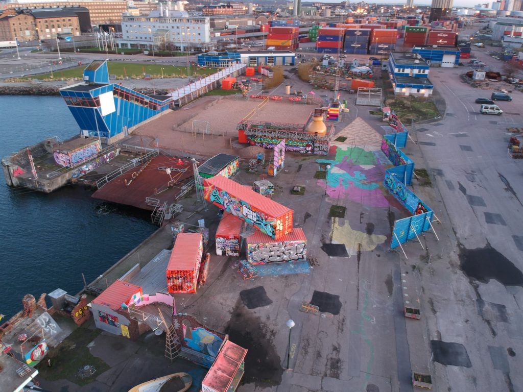
DCIM/100MEDIA/DJI_0347.JPG 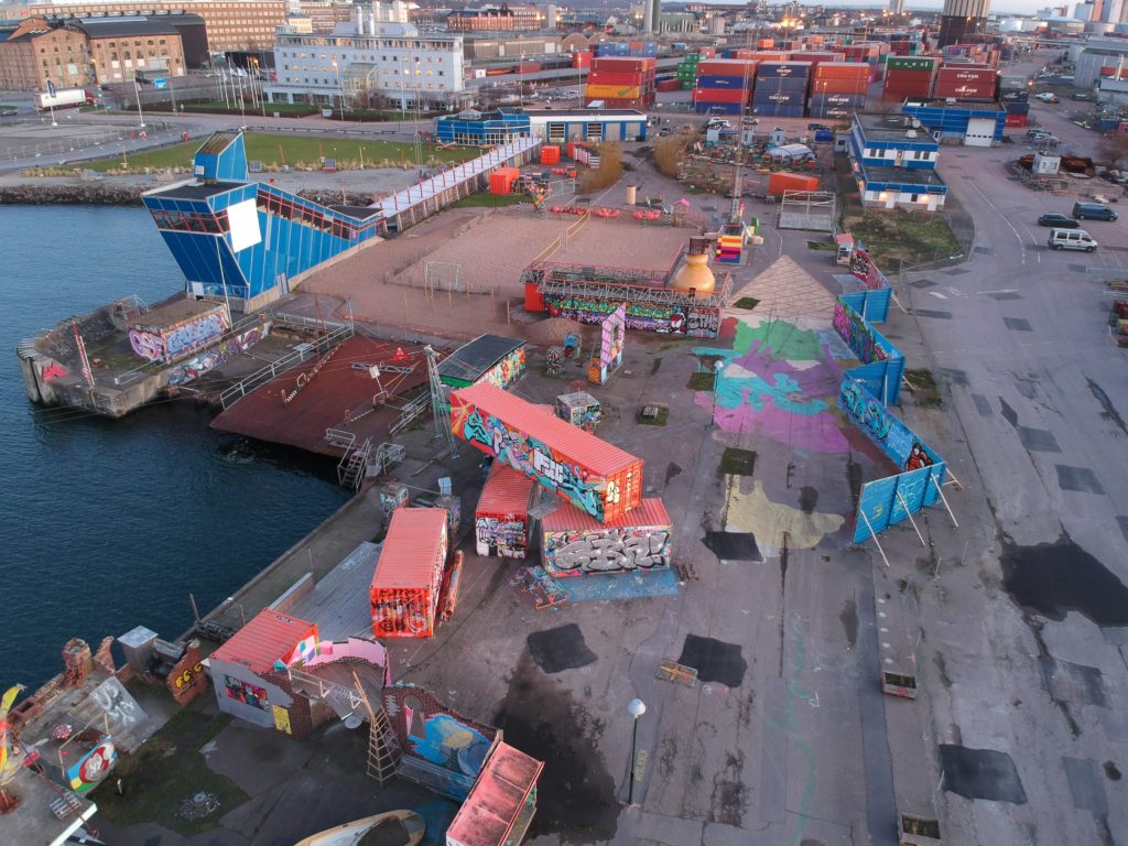
DCIM/100MEDIA/DJI_0348.JPG 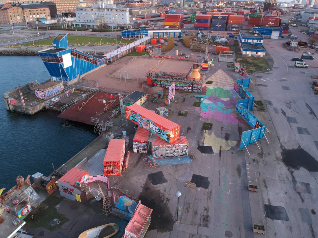
DCIM/100MEDIA/DJI_0349.JPG 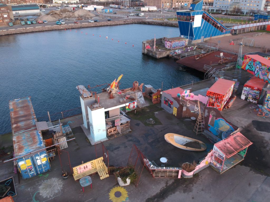
DCIM/100MEDIA/DJI_0350.JPG 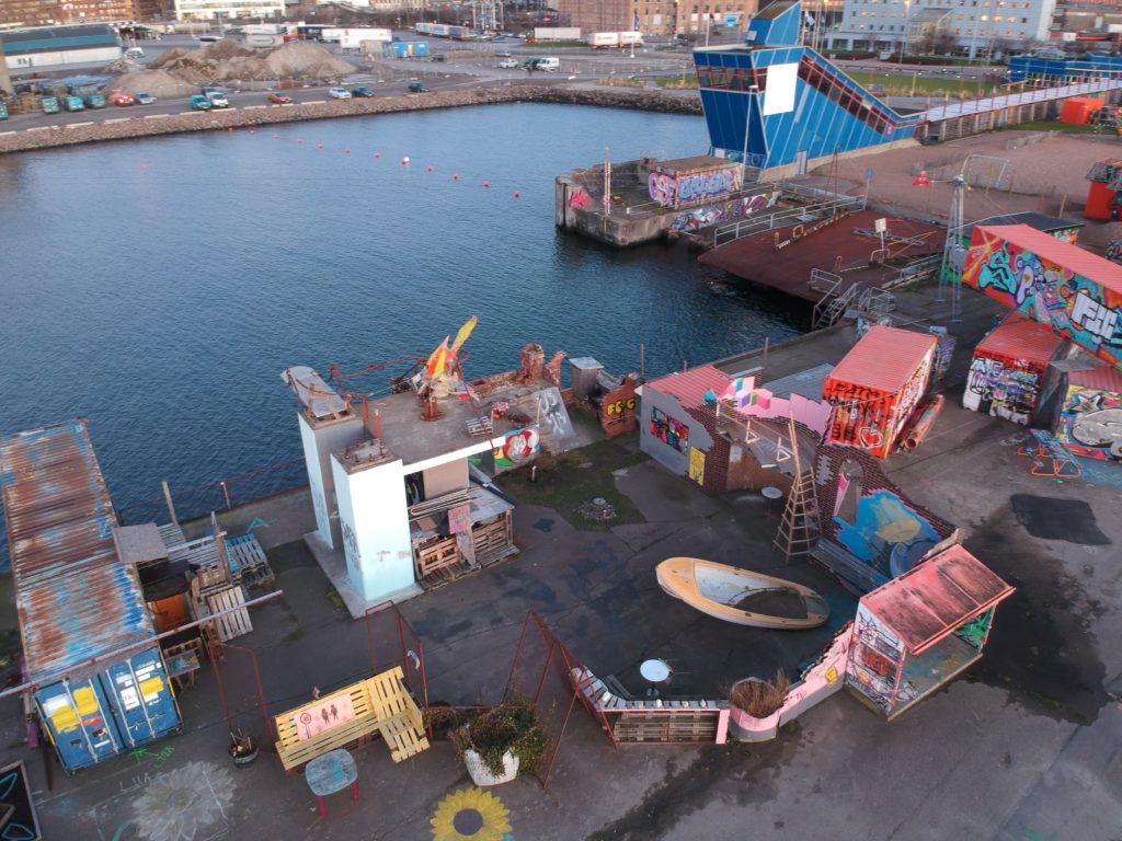
DCIM/100MEDIA/DJI_0351.JPG 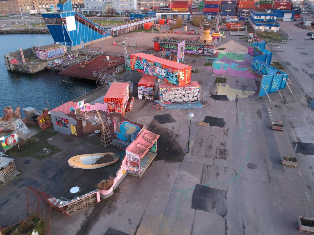
DCIM/100MEDIA/DJI_0352.JPG 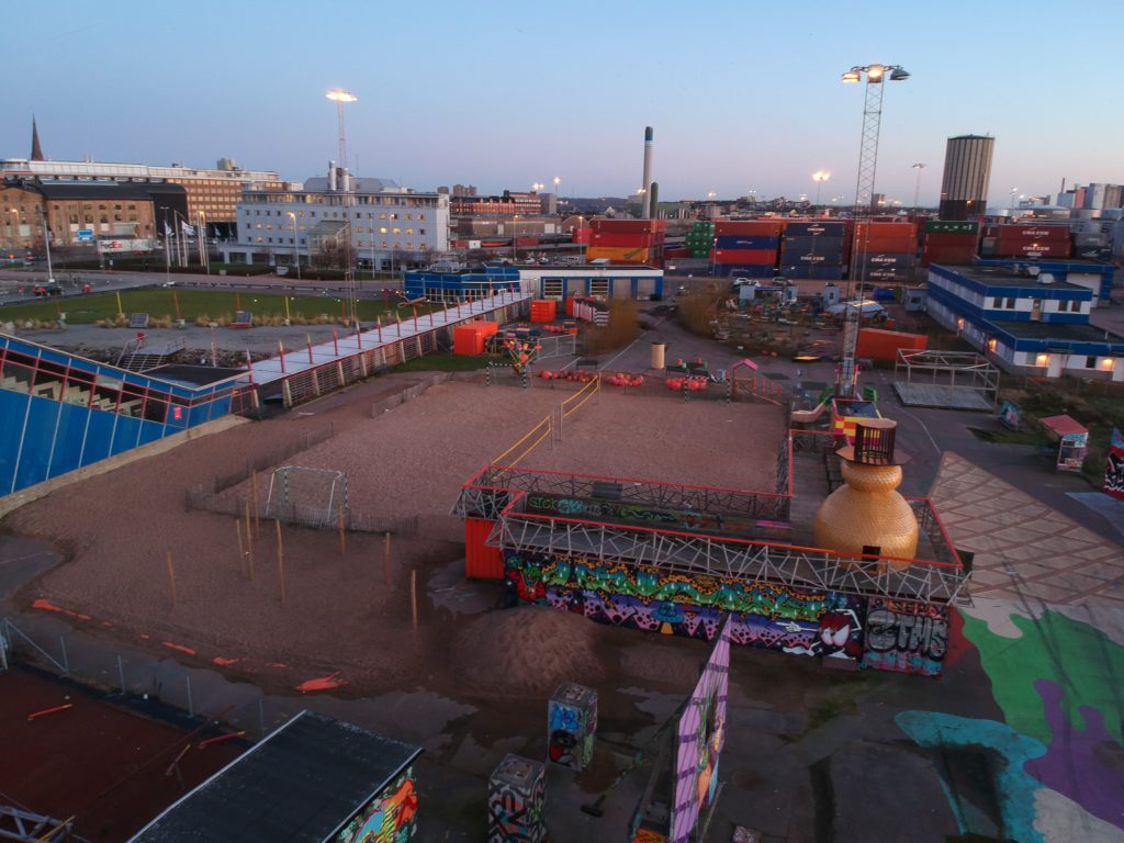
DCIM/100MEDIA/DJI_0354.JPG 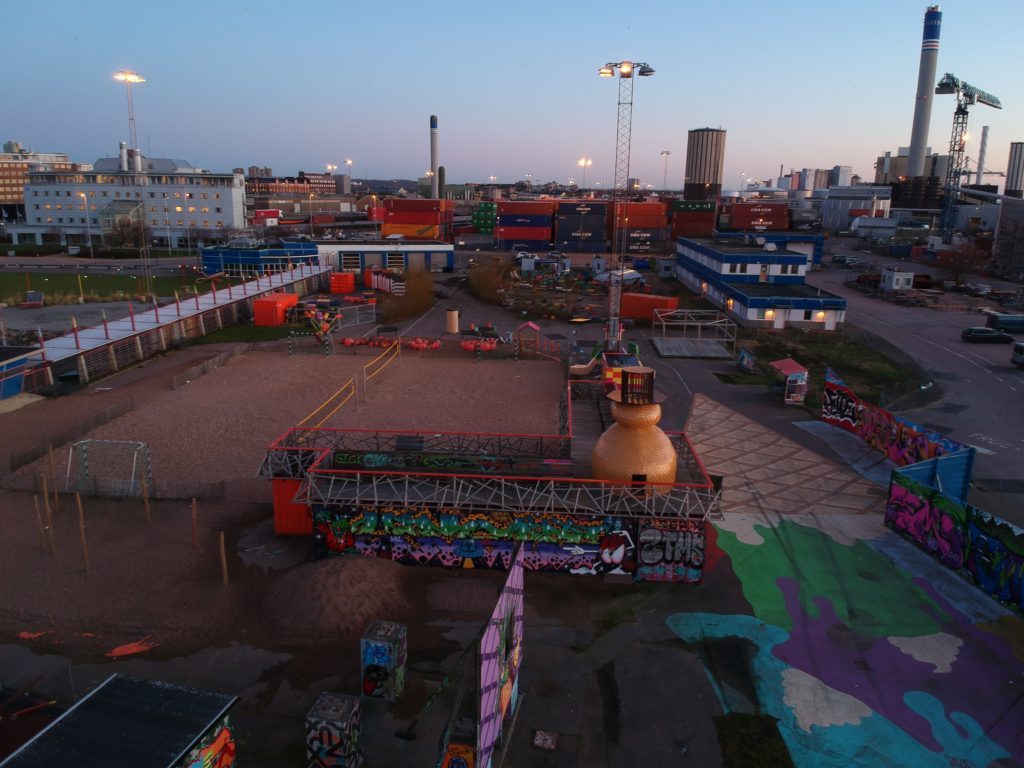
DCIM/100MEDIA/DJI_0355.JPG 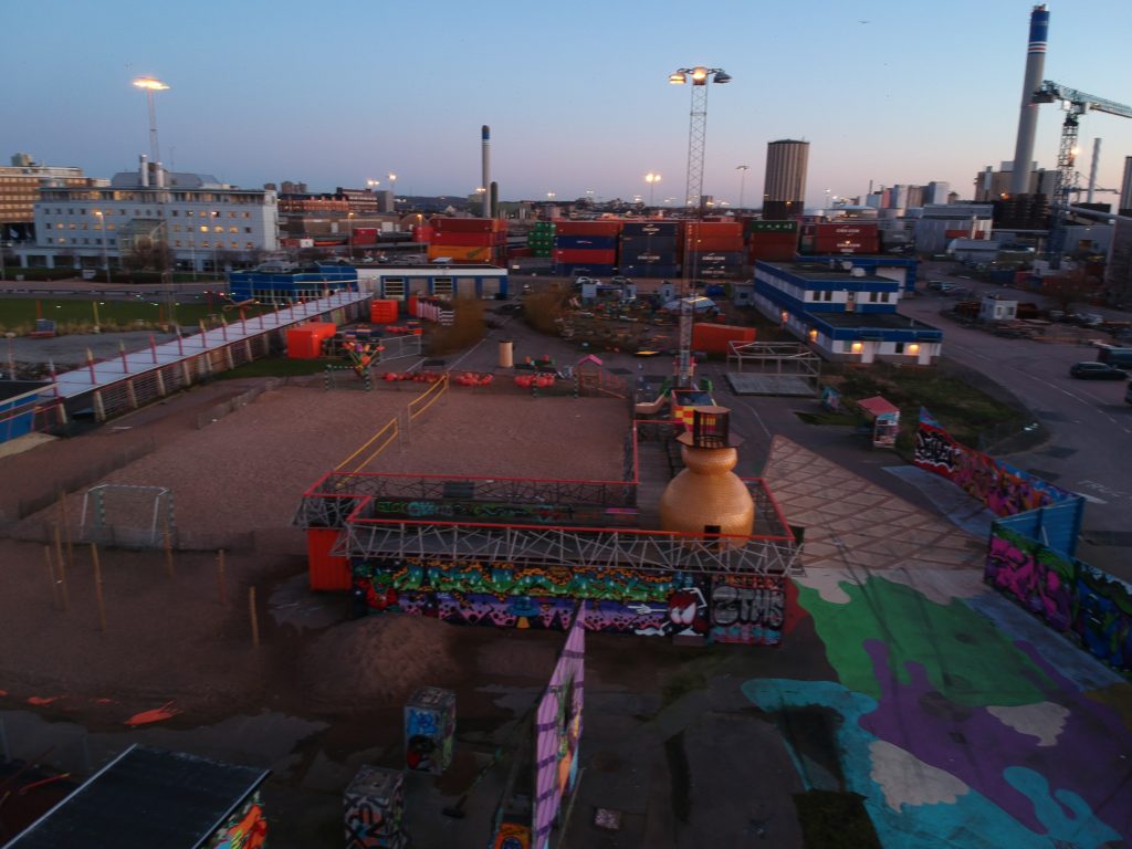
DCIM/100MEDIA/DJI_0356.JPG 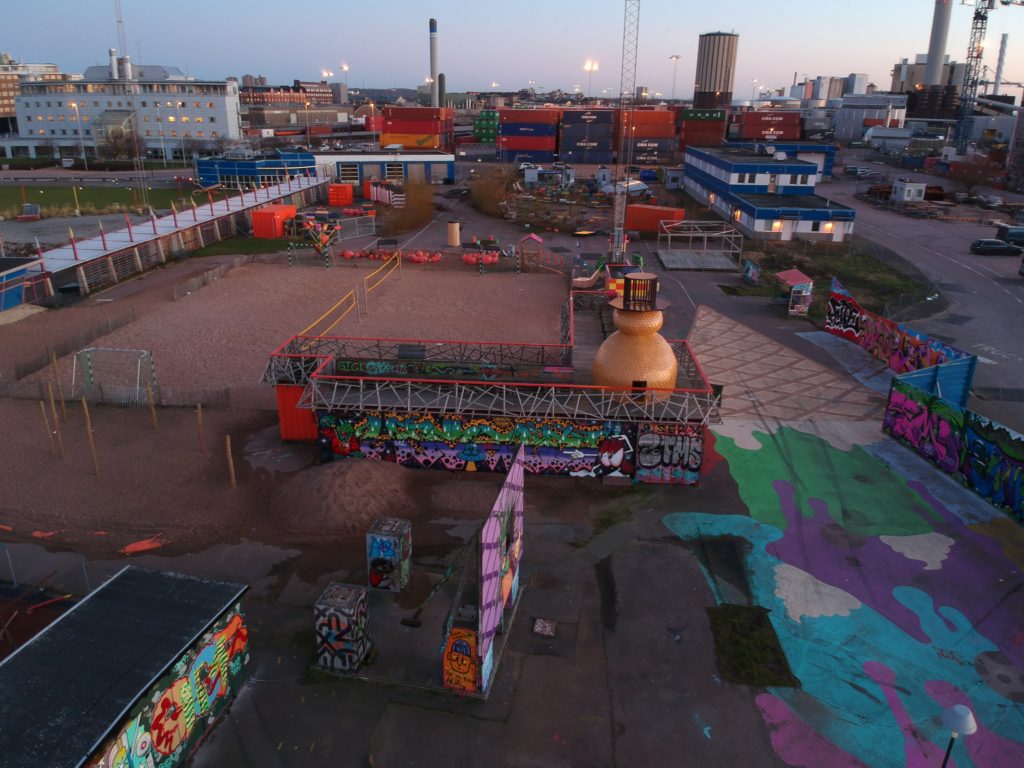
DCIM/100MEDIA/DJI_0357.JPG 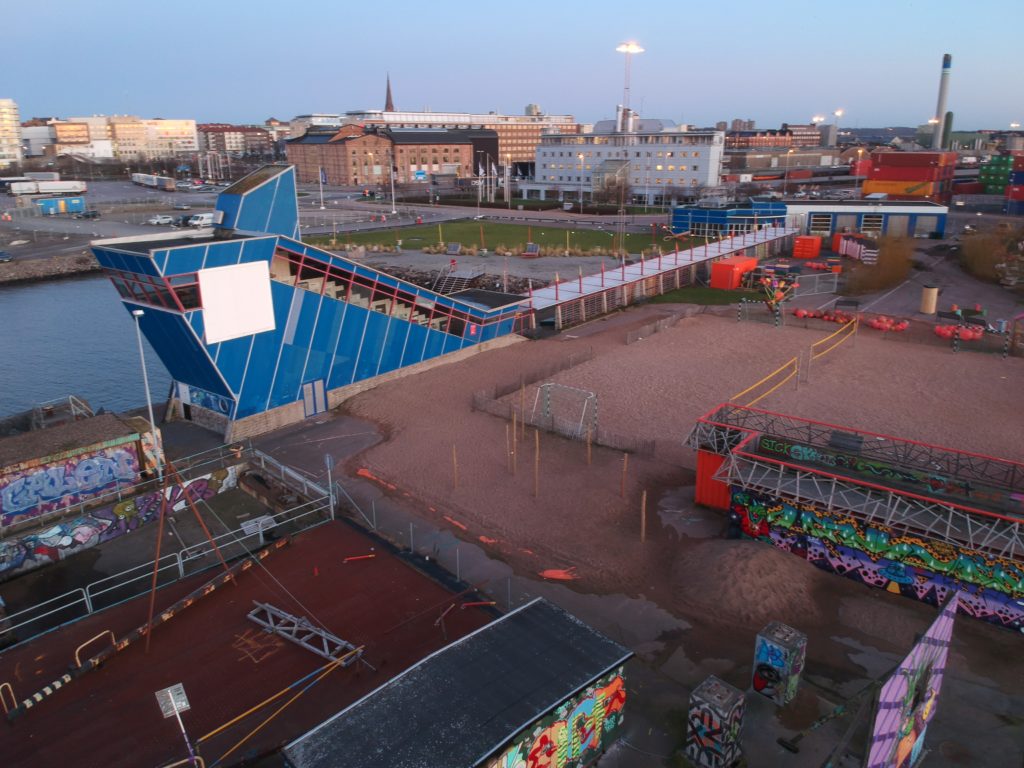
DCIM/100MEDIA/DJI_0358.JPG 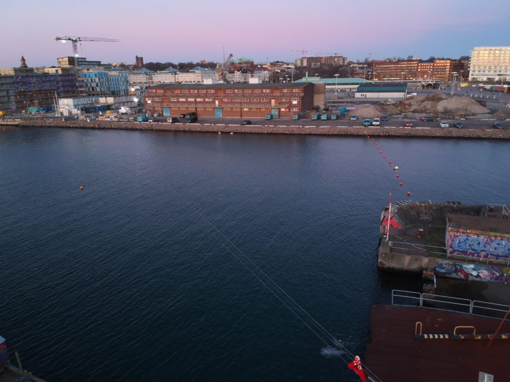
DCIM/100MEDIA/DJI_0359.JPG 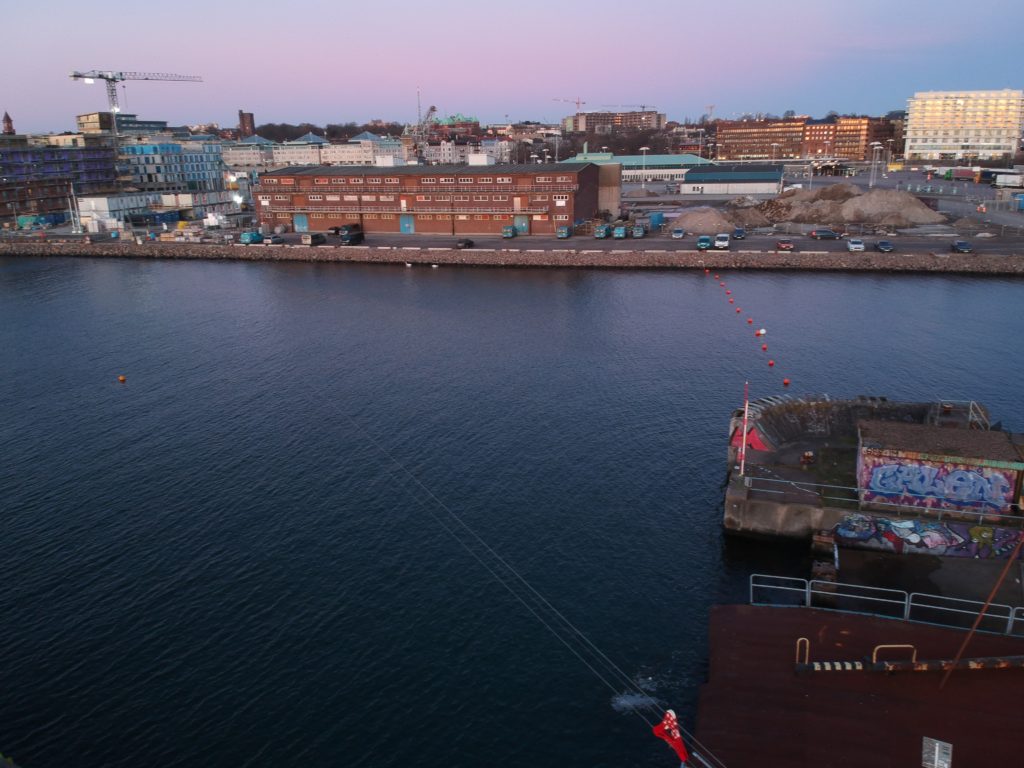
DCIM/100MEDIA/DJI_0360.JPG 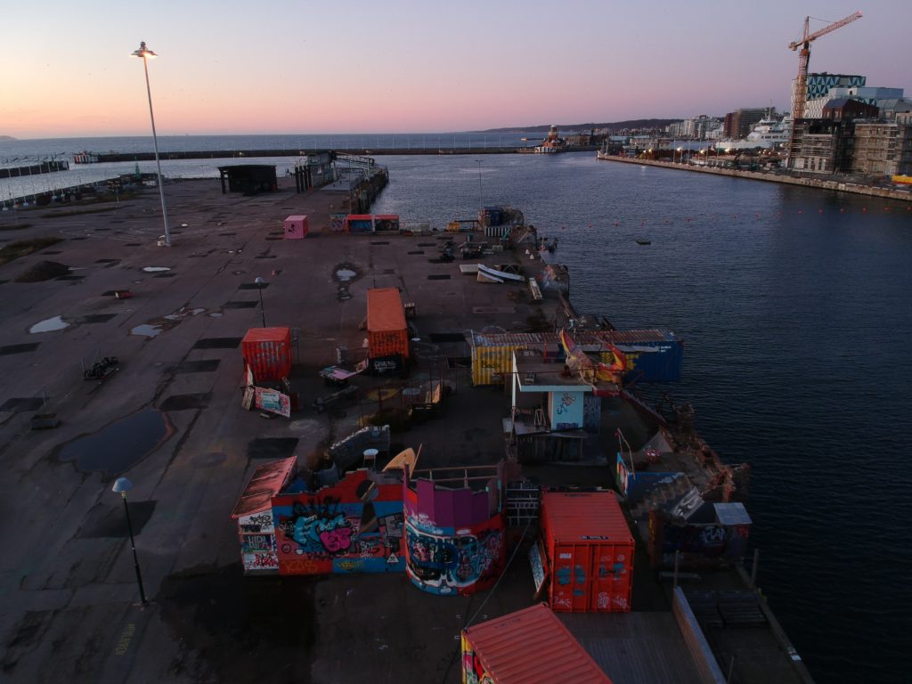
DCIM/100MEDIA/DJI_0361.JPG 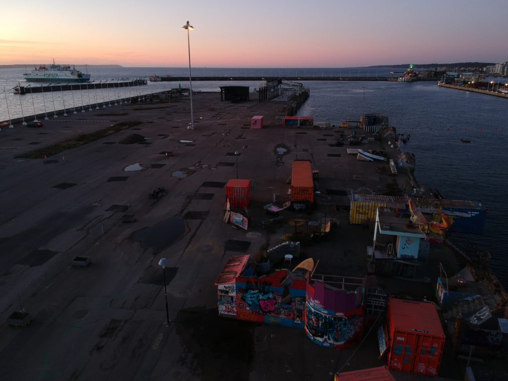
DCIM/100MEDIA/DJI_0362.JPG 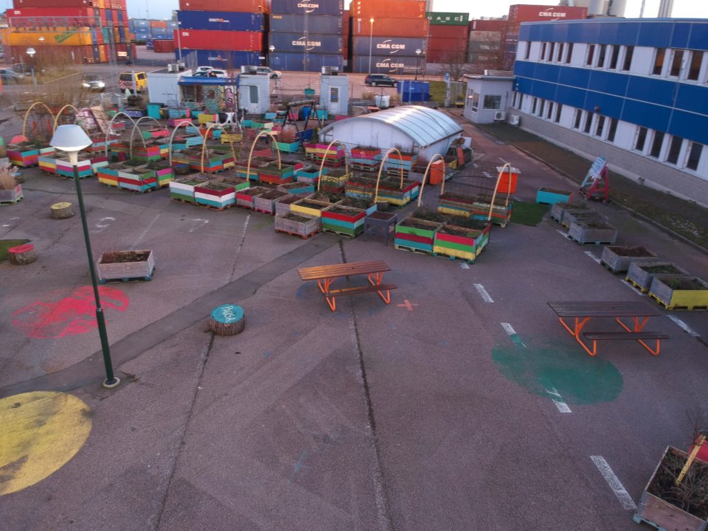
DCIM/100MEDIA/DJI_0364.JPG 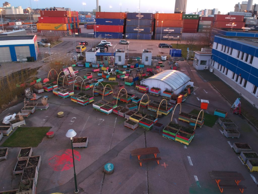
DCIM/100MEDIA/DJI_0365.JPG 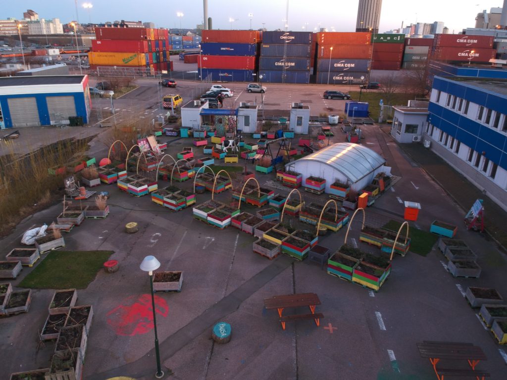
DCIM/100MEDIA/DJI_0366.JPG 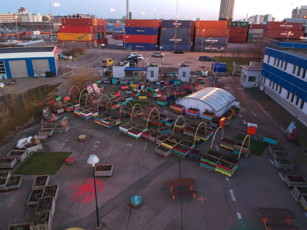
DCIM/100MEDIA/DJI_0367.JPG 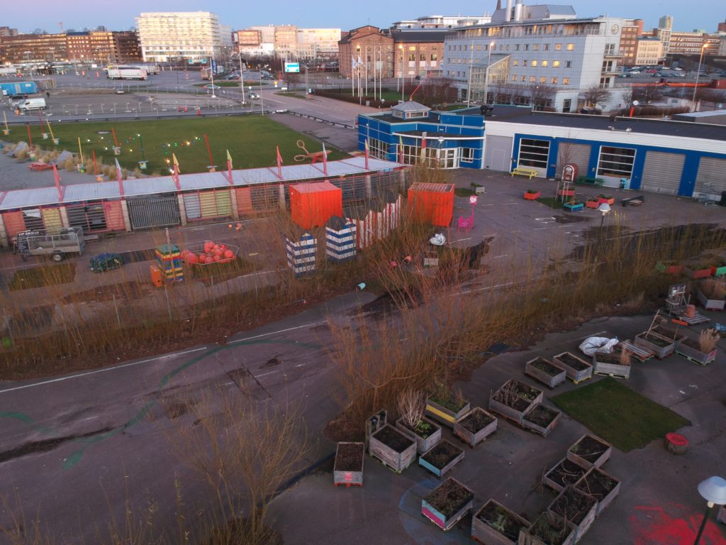
DCIM/100MEDIA/DJI_0369.JPG 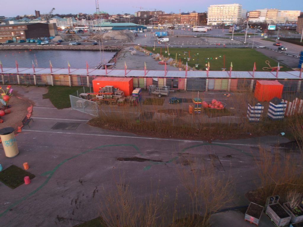
DCIM/100MEDIA/DJI_0370.JPG 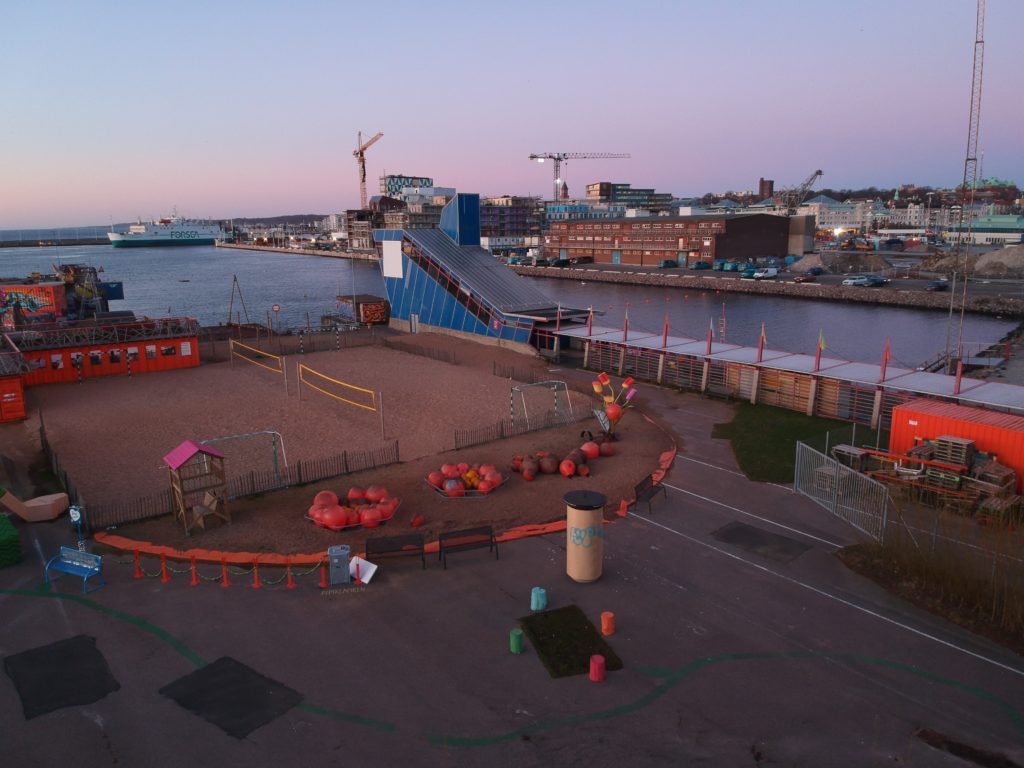
DCIM/100MEDIA/DJI_0372.JPG 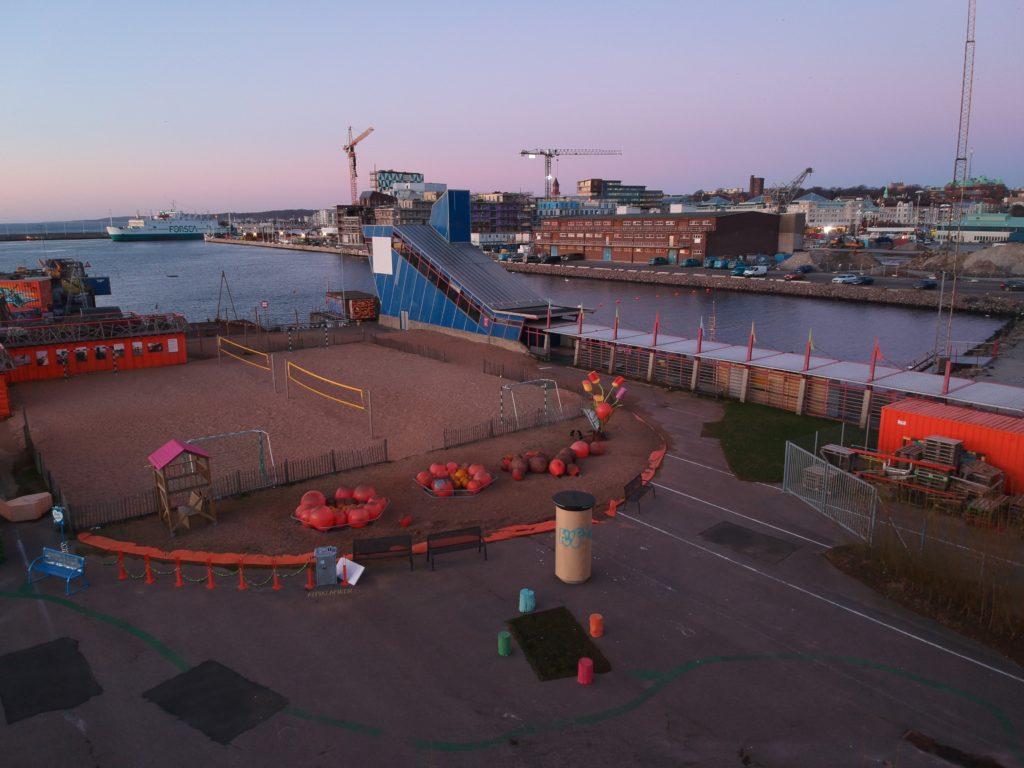
DCIM/100MEDIA/DJI_0373.JPG 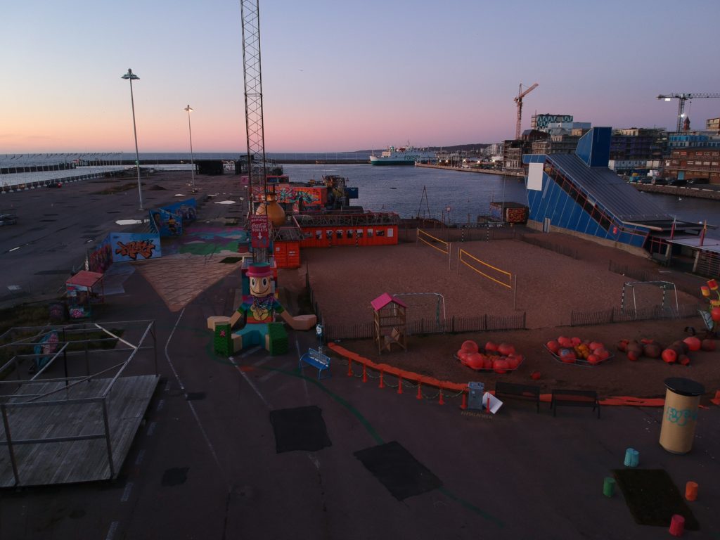
DCIM/100MEDIA/DJI_0374.JPG 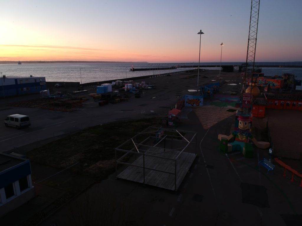
DCIM/100MEDIA/DJI_0375.JPG 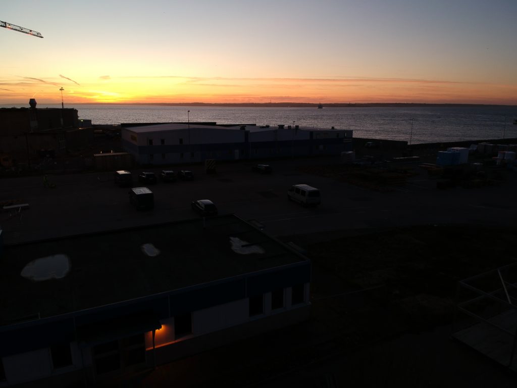
DCIM/100MEDIA/DJI_0376.JPG 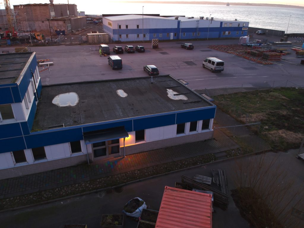
DCIM/100MEDIA/DJI_0377.JPG 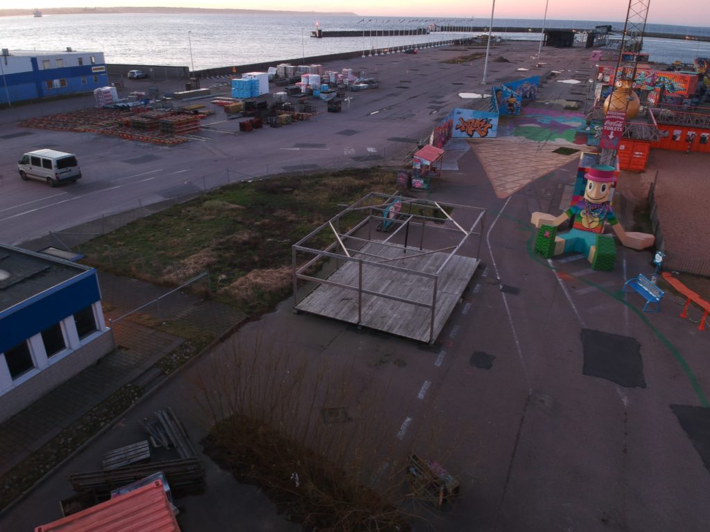
DCIM/100MEDIA/DJI_0378.JPG 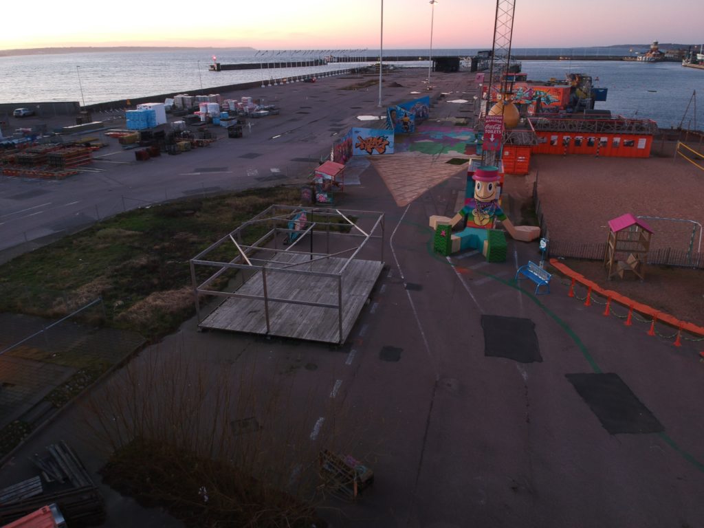
DCIM/100MEDIA/DJI_0379.JPG 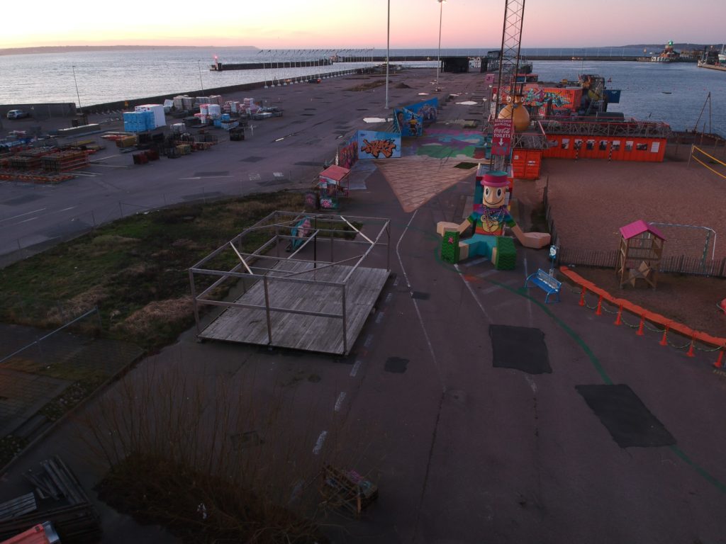
DCIM/100MEDIA/DJI_0380.JPG